

Method for manufacturing polymer electrolyte fuel cell
a polymer electrolyte and fuel cell technology, applied in the field of fuel cells, can solve the problems of insufficient and non-uniform contact between the polymer electrolyte and the catalyst, inability to ensure inability to achieve sufficient reaction area at the interface between the electrode and the ion-exchange membrane,
- Summary
- Abstract
- Description
- Claims
- Application Information
AI Technical Summary
Benefits of technology
Problems solved by technology
Method used
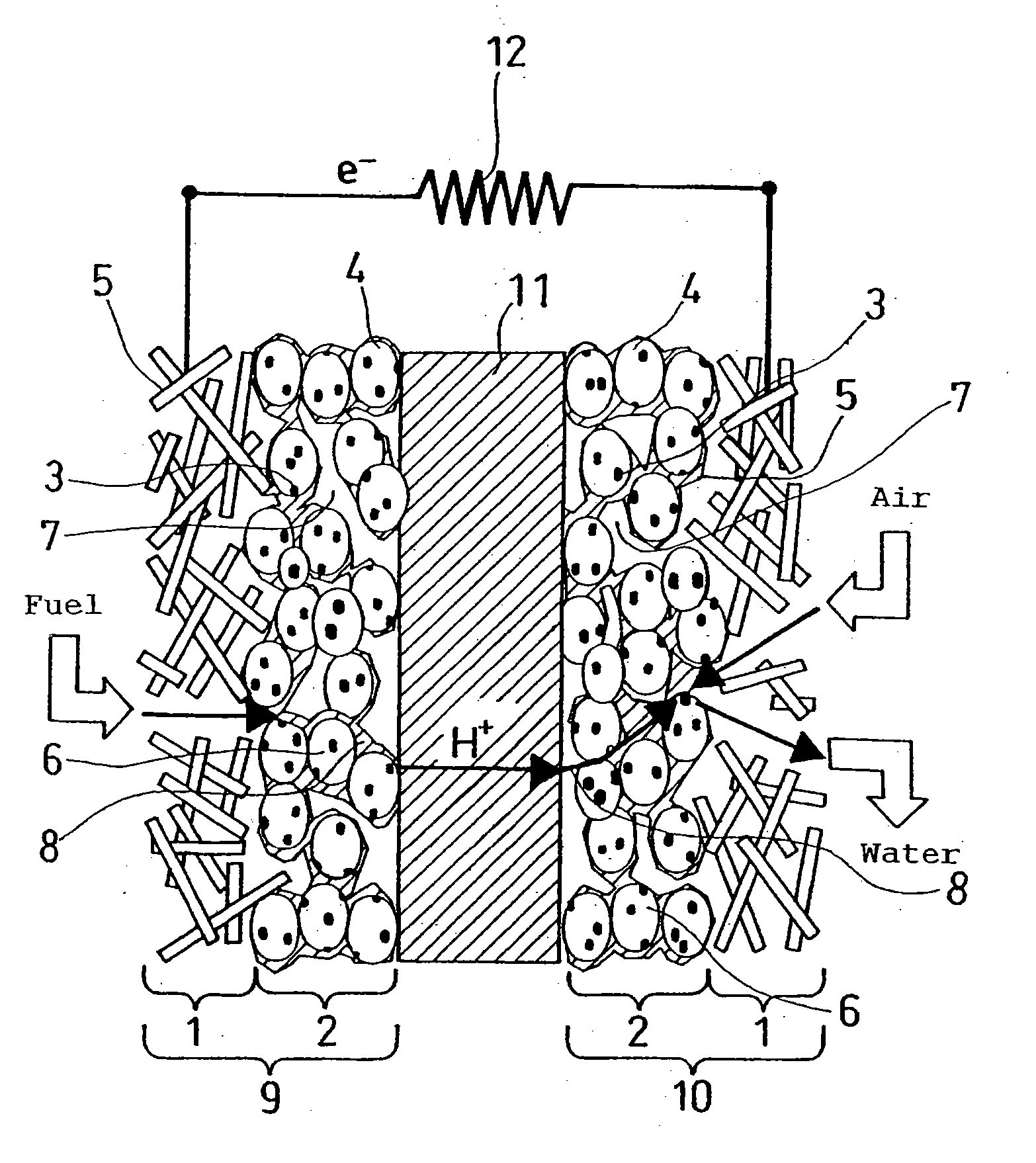
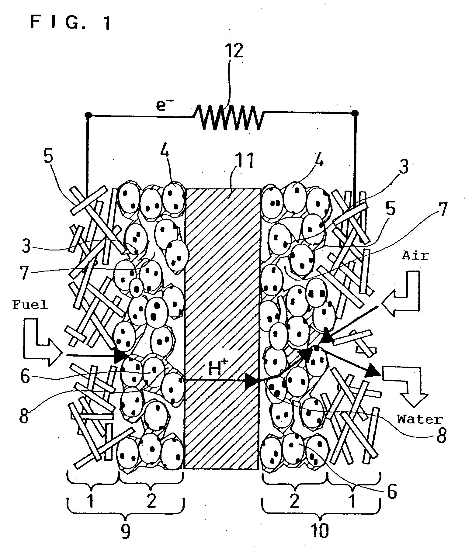
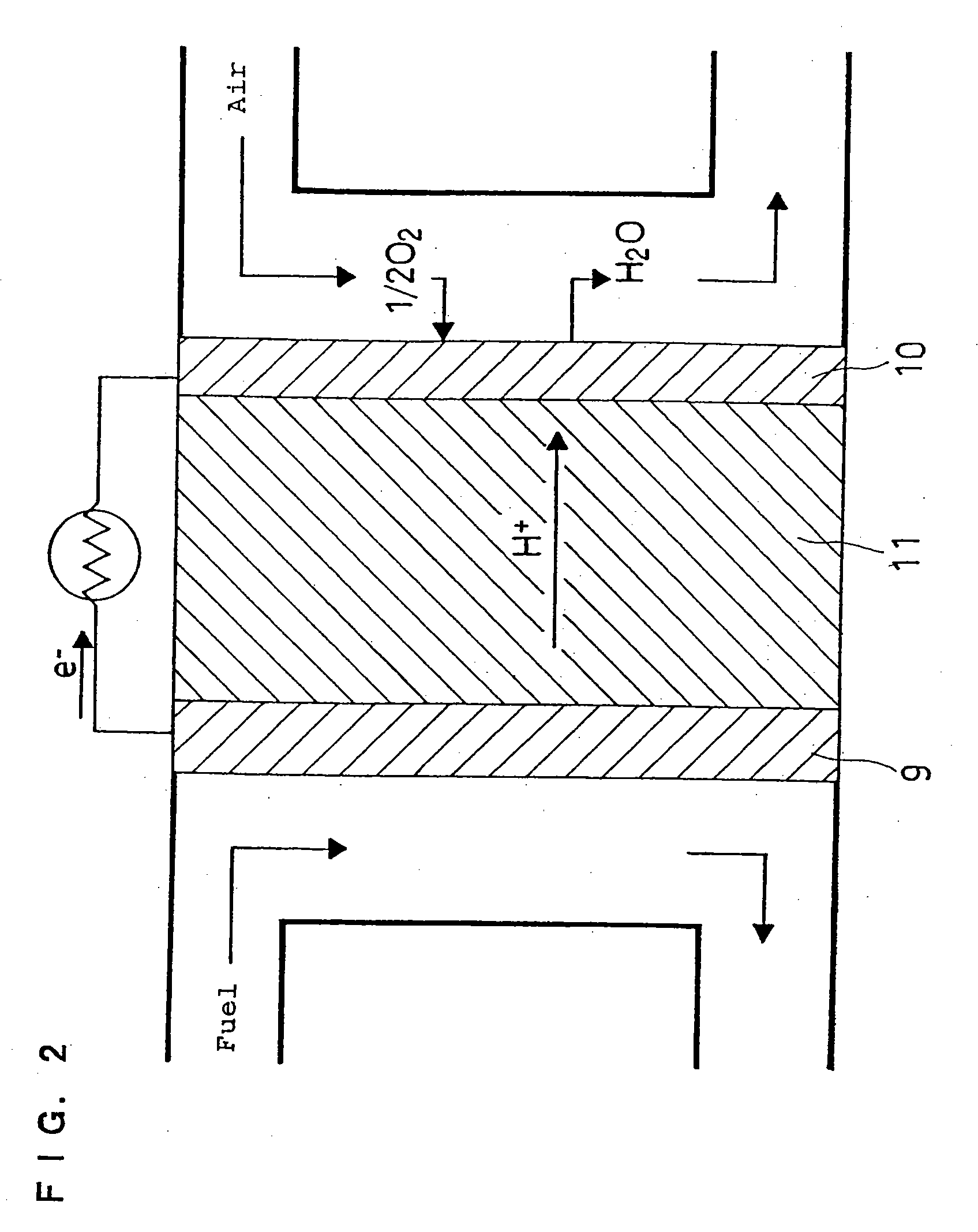
Image

Examples
example 1
[0098] First, the first carbon particles, acetylene black (DENKA BLACK manufactured by Denki Kagaku Kogyo K.K.), having a specific surface area of 68 m2 / g and a DBP oil adsorption of 175 ml / 100 g were caused to support 40% by weight of a platinum catalyst. The resulting catalyst particles were dispersed in butyl acetate to prepare a dispersion. This dispersion and an alcohol dispersion of polymer electrolyte (“9% FSS solution” (trade name) manufactured by Asahi Glass Co., Ltd.) were mixed in a weight ratio of 1:1.15 to produce a colloid of the polymer electrolyte and prepare a mixed liquid containing the carbon particles adsorbing the colloid.
[0099] Meanwhile, the second carbon particles, ketjen black (Ketjen Black EC manufactured by Ketjen Black International Co.), having a specific surface area of 800 m2 / g and a DBP oil adsorption of 360 ml / 100 g were caused to support 50% by weight of a platinum catalyst. The resulting catalyst particles were dispersed in an alcohol dispersion o...
example 2
[0102] A membrane-catalyst layer assembly was formed by applying the same catalyst layer ink as in Example 1 on both surfaces of a polymer electrolyte membrane (Nafion 112 membrane manufactured by E.I. du Pont de Nemours and Company). Subsequently, cell B was assembled in the same manner as in Example 1, except that a gas diffusion layer carbon paper (Carbon Paper TGPH-060 manufactured by Toray Industries, Inc.) was integrally joined to both surfaces of this membrane-catalyst layer assembly by application of a pressure of 4 MPa / cm2 at 150° C. to form a membrane-electrode assembly.
example 3
[0103] A catalyst layer was formed by applying the same catalyst layer ink as in Example 1 on a surface of a transfer film made of polypropylene. This catalyst layer was transferred to both surfaces of a polymer electrolyte membrane (“GORESELECT membrane” manufactured by Japan Gore-Tex Inc.) by application of a pressure of 2 MPa / cm2 at 130° C. to prepare a membrane-catalyst layer assembly. A gas diffusion layer carbon paper (Carbon Paper TGPH-060 manufactured by Toray Industries, Inc.) was integrally joined to both of the catalyst layers of this membrane-catalyst layer assembly by application of a pressure. Thus, a membrane-electrode assembly was formed, and cell C was assembled.
PUM
| Property | Measurement | Unit |
|---|---|---|
| median diameter | aaaaa | aaaaa |
| temperature | aaaaa | aaaaa |
| dielectric constant | aaaaa | aaaaa |
Abstract
Description
Claims
Application Information