Medical-technology valve device for suction and/or flushing lines of medical instruments

Inactive Publication Date: 2006-10-12
KARL STORZ GMBH & CO KG
View PDF11 Cites 56 Cited by
  • Summary
  • Abstract
  • Description
  • Claims
  • Application Information

AI Technical Summary

Benefits of technology

[0015] It is further proposed with the invention that the pitch of the thread, which transmits the rotary motion of the servo drive into the axial motion of the piston, is configured in such a way that the angle of rotation of the servo drive is proportional to the blocking or release of the through bore-hole, that is, proportional to the flow-through quantity, so that the thread preferably has a self-restricting action in order to prevent the through-flowing medium from affecting the

Problems solved by technology

The diversion of the stream in this construction, however, causes severe turbulence, which prevents a reproducible adjustment of the volume flow that is to be regulated.
It is a disadvantage in valve devices configured as fa

Method used


Image

  • Medical-technology valve device for suction and/or flushing lines of medical instruments
  • Medical-technology valve device for suction and/or flushing lines of medical instruments
  • Medical-technology valve device for suction and/or flushing lines of medical instruments

Examples


Embodiment Construction

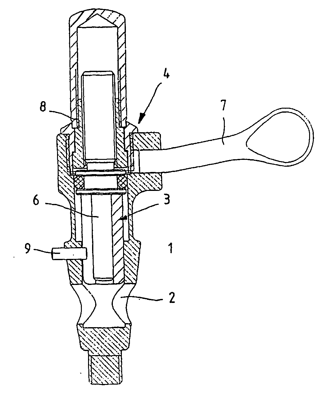
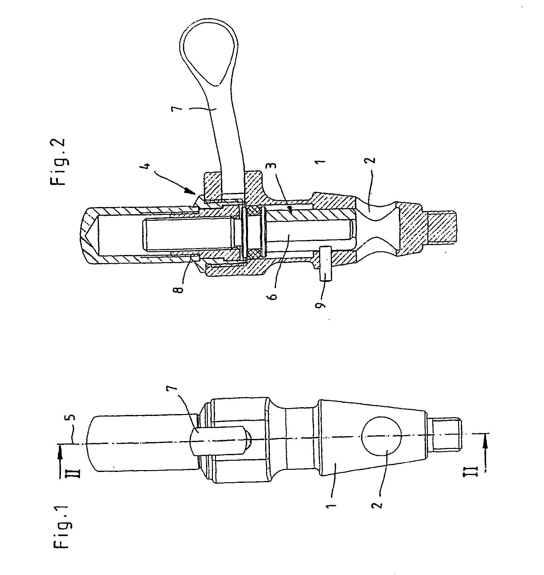
[0024] The medical-technology valve device illustrated in FIGS. 1 through 6 consists essentially of a valve housing 1 with a through bore-hole 2, onto which suction and / or flushing lines (not illustrated) of medical instruments can be connected, as well as a valve body 3 movably positioned in the valve housing 1.

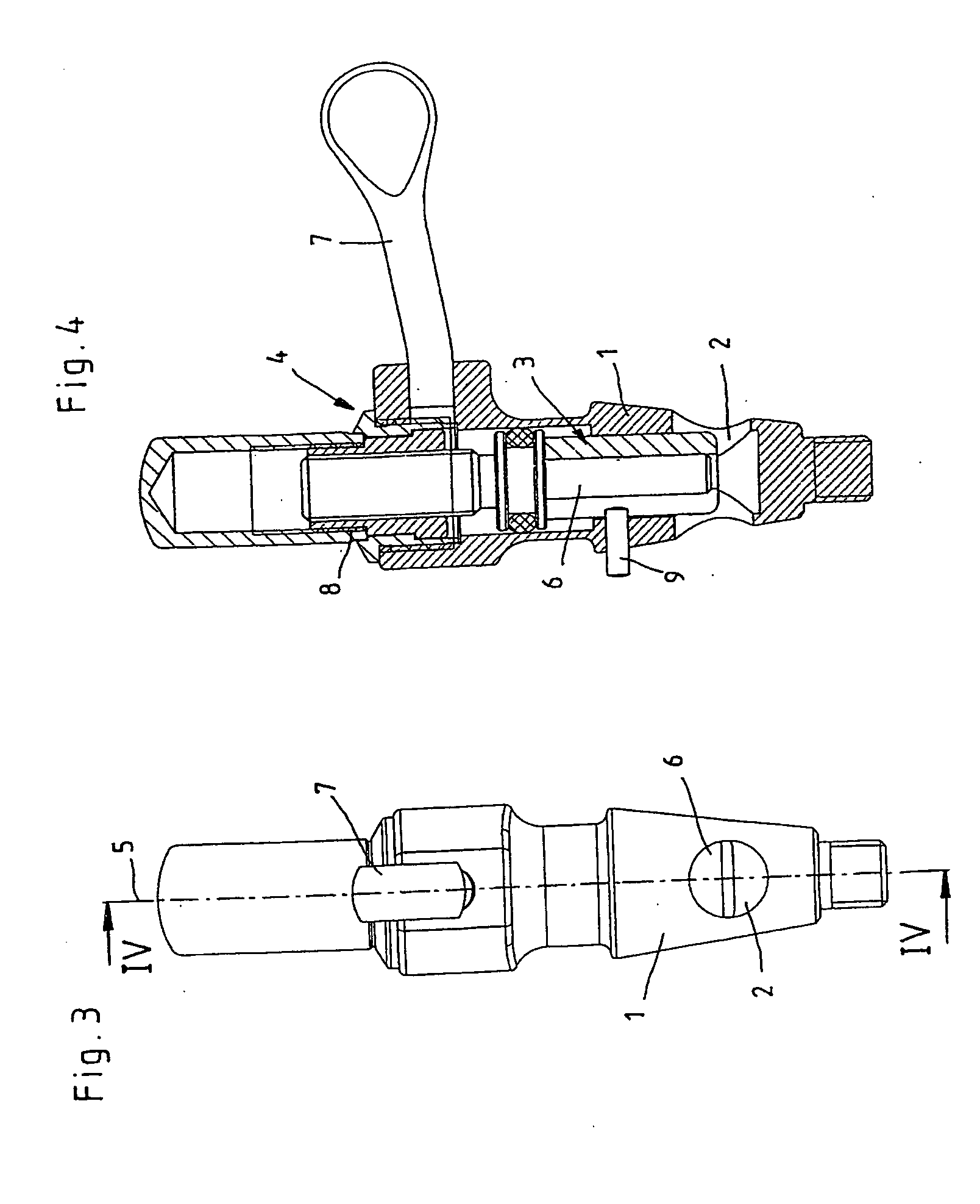
[0025] The valve body 3, as can be seen in FIGS. 1 through 4, is positioned in the valve housing 1 so that it can be displaced, by means of a servo drive 4, in the direction of the longitudinal axis 5 of the valve housing 1 between an open position (FIGS. 1 and 2) that releases the through bore-hole 2 and a closed position that closes off the through bore-hole. FIGS. 3 and 4 shows the valve body 3 in a half-opened or half-closed intermediate position.

[0026] As can be seen from the illustrations, the valve body 3 is configured as a closed piston 6, which has no through bore-hole of its own, so that every displacement of the piston 6 by the servo drive 4 signifies a direct c...


PUM


Abstract

The invention relates to a medical-technology valve device for suction and/or flushing lines of medical instruments, particularly instruments for endoscopic surgery, having a valve housing equipped with a through bore-hole and having a valve body, movably positioned in the valve housing, by which valve body the through bore-hole can be locked and opened again, and where the valve body is configured as a piston that can be displaced essentially perpendicularly to the through bore-hole by means of a servo drive, so that a rotary movement of the servo drive can be transformed into an axial movement of the piston. To produce a medical-technology valve device that makes possible a reproducible adjustment of the flow volume that is to be regulated, while allowing a reduction of turbulence, it is proposed with the invention that the servo drive is configured as a hand lever that can rotate around the longitudinal axis of the piston and can be displaced to move the piston from the position that frees the through bore-hole into the position that closes the through bore-hole by an angle of 90 degrees with respect to the longitudinal axis of the piston.

Description

CROSS-REFERENCE TO RELATED APPLICATIONS [0001] The present application is a continuation of pending International patent application PCT / EP2005 / 004388 filed on Apr. 23, 2005 which designates the United States and claims priority from German patent application 10 2004 020 071.8 filed on Apr. 24, 2004, the content of which is incorporated herein by reference.FIELD OF THE INVENTION [0002] The invention relates to a medical-technology valve device for suction and / or flushing lines of medical instruments, particularly instruments for endoscopic surgery, having a valve housing equipped with a through bore-hole and having a valve body, movably positioned in the valve housing, by which valve body the through bore-hole can be locked and released again, and where the valve body is configured as a piston that can be displaced essentially perpendicularly to the through bore-hole by means of a servo drive, so that a rotary movement of the servo drive can be transformed into an axial movement of ...

Claims


Application Information

Patent Timeline
IPC IPC(8): A61B1/12A61M1/00A61M5/168A61M39/22F16K3/24F16K31/50
CPCA61M1/0043A61M39/22A61M5/16813A61M1/0064A61M1/7413A61M1/774
Inventor EISENKOLB, PETEREFINGER, ANDREAS
Owner KARL STORZ GMBH & CO KG
Why Eureka
Try Eureka