

Working machine having prime mover control device
- Summary
- Abstract
- Description
- Claims
- Application Information
AI Technical Summary
Benefits of technology
Problems solved by technology
Method used
Image

Examples
first embodiment
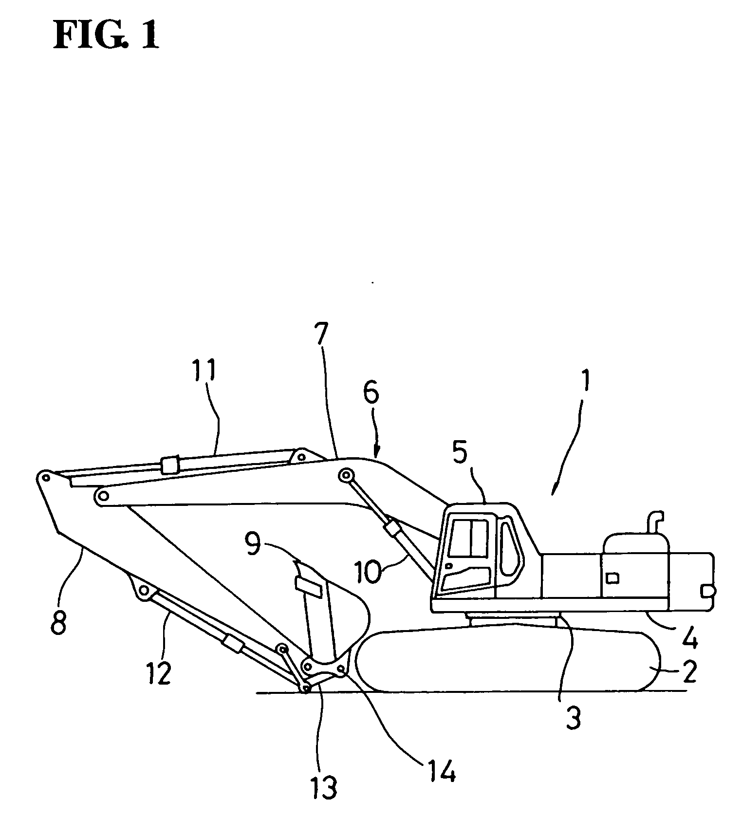
[0024]FIG. 1 shows a side view of a hydraulic excavator according to the invention.
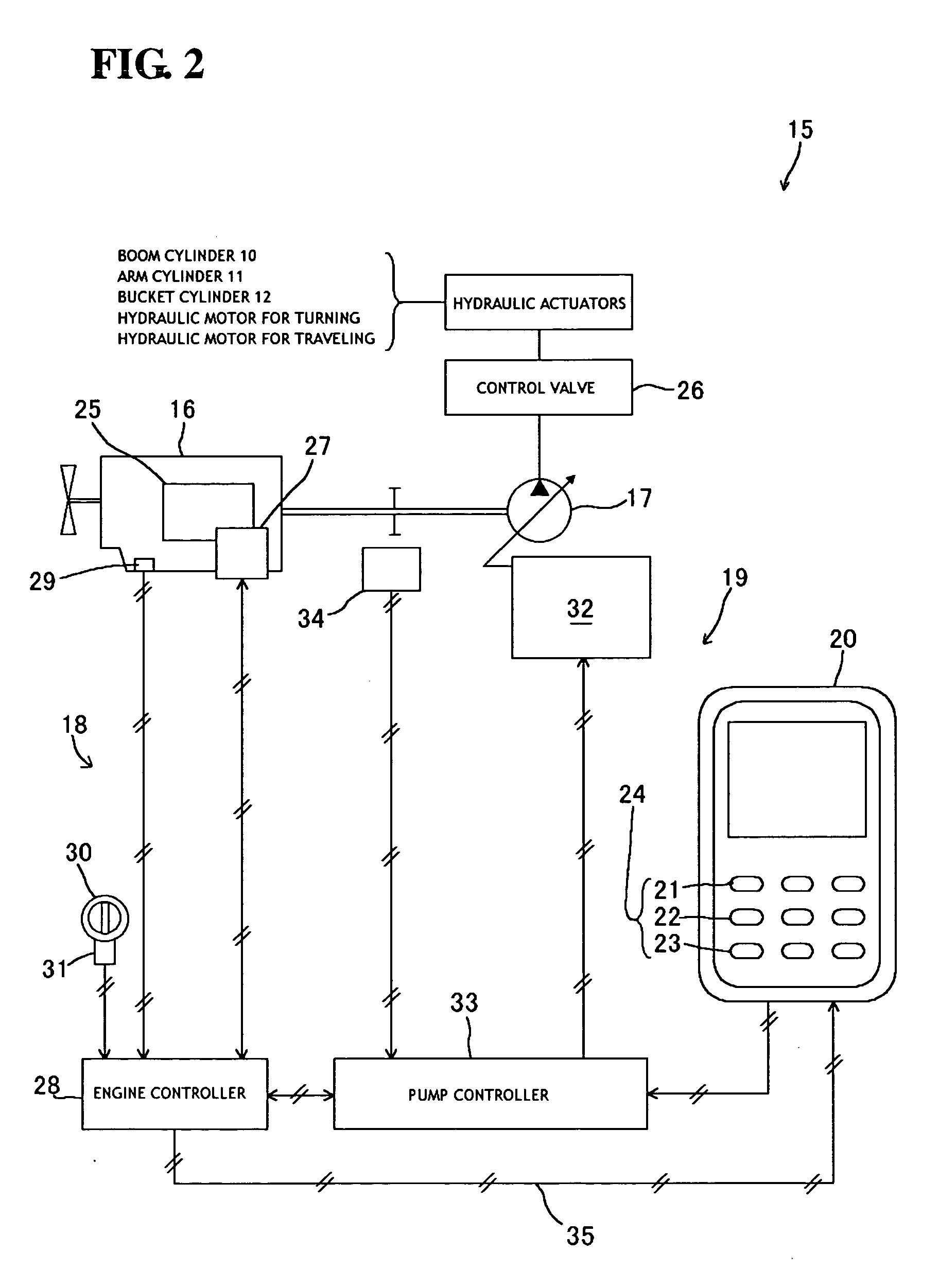
[0025] The hydraulic excavator 1 has lower machinery 2 designed to freely travel, being driven by a hydraulic motor for traveling (not shown); upper machinery 4 mounted on the lower machinery 2 through a swivel 3 which uses a hydraulic motor for turning (not shown) as a driving source; and an implement 6 attached to the upper machinery 4. The implement 6 is constituted by a boom 7, an arm 8 and a bucket 9 which are respectively pivotally arranged in this order from a side of the upper machinery 4. The boom 7, the arm 8 and the bucket 9 are pivotally operated by expansion / contraction of a boom cylinder 10, an arm cylinder 11 and a bucket cylinder 12, respectively. The upper machinery 4 includes an operator's cab 5 which has, therein, an operating system (not shown) for operating the hydraulic actuators (i.e., the hydraulic motor for traveling; hydraulic motor for turning; boom cylinder 10, arm cylinder...
third embodiment
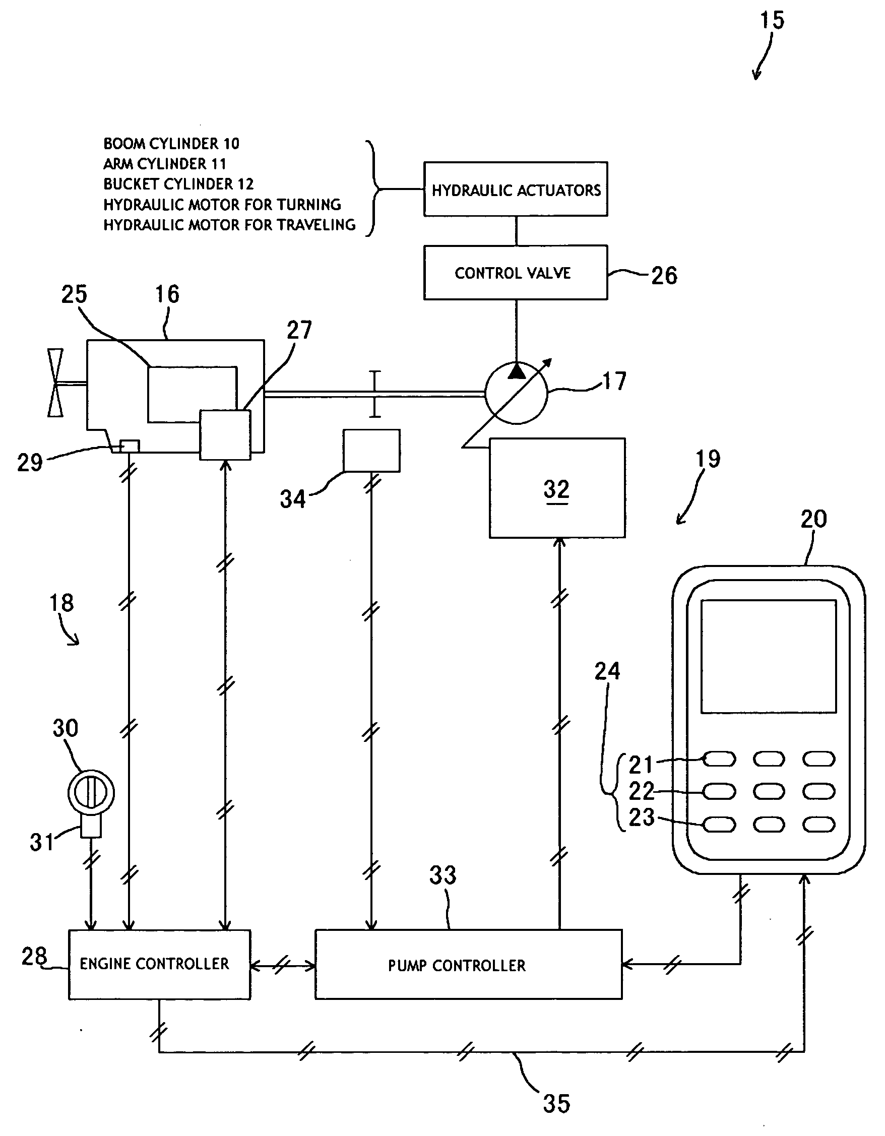
[0043] The engine 16 is equipped with the accumulator (common-rail) fuel injection device 40. The fuel injection device 40 itself is publicly known and therefore a detailed explanation of it with reference to the drawings is omitted herein. The fuel injection device 40 is of a type in which fuel is accumulated in a common rail by a fuel force feed pump and the fuel is injected from an injector by opening / closing of an electromagnetic valve. The fuel injection device 40 is formed such that fuel injection characteristics are determined based on a drive signal sent from the engine controller 28 to the electromagnetic valve so that arbitrary injection characteristics over the range from the low-speed region to high-speed region of the engine 16 can be obtained. In the third embodiment, an electronically controlled injection system, which is composed of the fuel injection device 40, the engine controller 28 and instruments including various sensors, constitutes the engine control device ...
fourth embodiment
[0051] In the fourth embodiment, if the operator turns ON the lifting mode selector switch 23 among the operation mode selector switches 24, the engine output torque characteristic line ELA″ shown in FIG. 8 is set, while the pump absorbing torque characteristic line PLA′ is set which matches the engine output toque characteristic line ELA″ at the output torque point Mc on the equi-horse-power control line Le. On the other hand, if the operator turns ON the active mode selector switch 21 among the operation mode selector switches 24, the engine output torque characteristic line ELB shown in FIG. 8 is set, while the pump absorbing torque characteristic line PLB is set which matches the engine output torque characteristic line ELB at the output torque point Mb at which the output of the engine 16 has a maximum.
[0052] In the fourth embodiment, if the lifting mode is selected, the load starts to increase from the unloaded condition, so that the engine 16 is once driven according to the i...
PUM
 Abstract
Description
Claims
Application Information