Control of a gas turbine with hot-air reactor

Inactive Publication Date: 2006-10-19
ALSTOM SWEDEN +1
View PDF2 Cites 5 Cited by
  • Summary
  • Abstract
  • Description
  • Claims
  • Application Information

AI Technical Summary

Benefits of technology

[0009] Arranging the AZEP reactor separate from the gas turbine makes it possible to

Problems solved by technology

One problem that has to be overcome in order to drive a gas turbine with an MCM reactor is how to control the plant.
Such control is impossible with the ver

Method used


Image

  • Control of a gas turbine with hot-air reactor
  • Control of a gas turbine with hot-air reactor
  • Control of a gas turbine with hot-air reactor

Examples


Embodiment Construction

OF EMBODIMENTS OF THE INVENTION

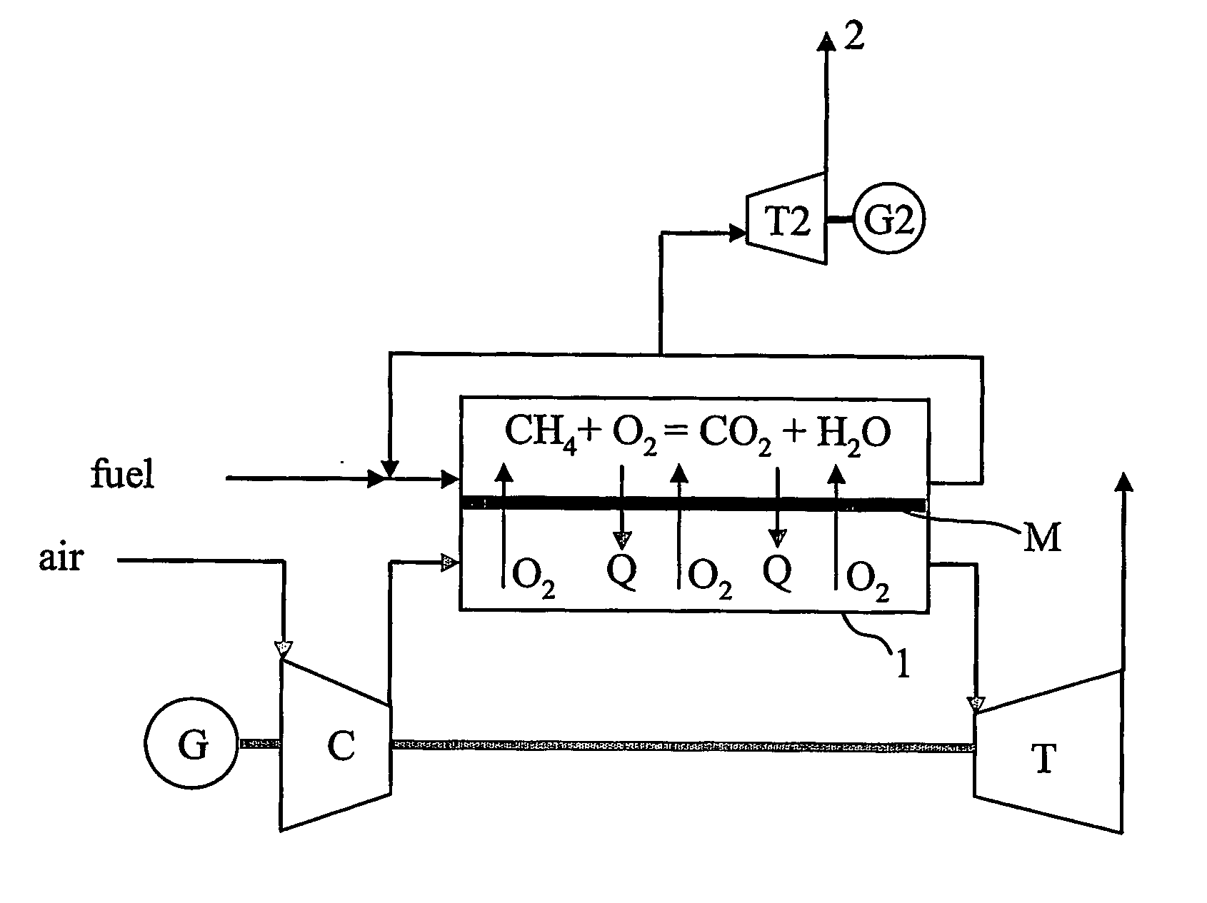
[0017] The invention will be described below with reference to the drawings attached. An arrangement in the form of a gas turbine plant, which is controlled according to the aspects of the invention, is shown in FIG. 1 described above.

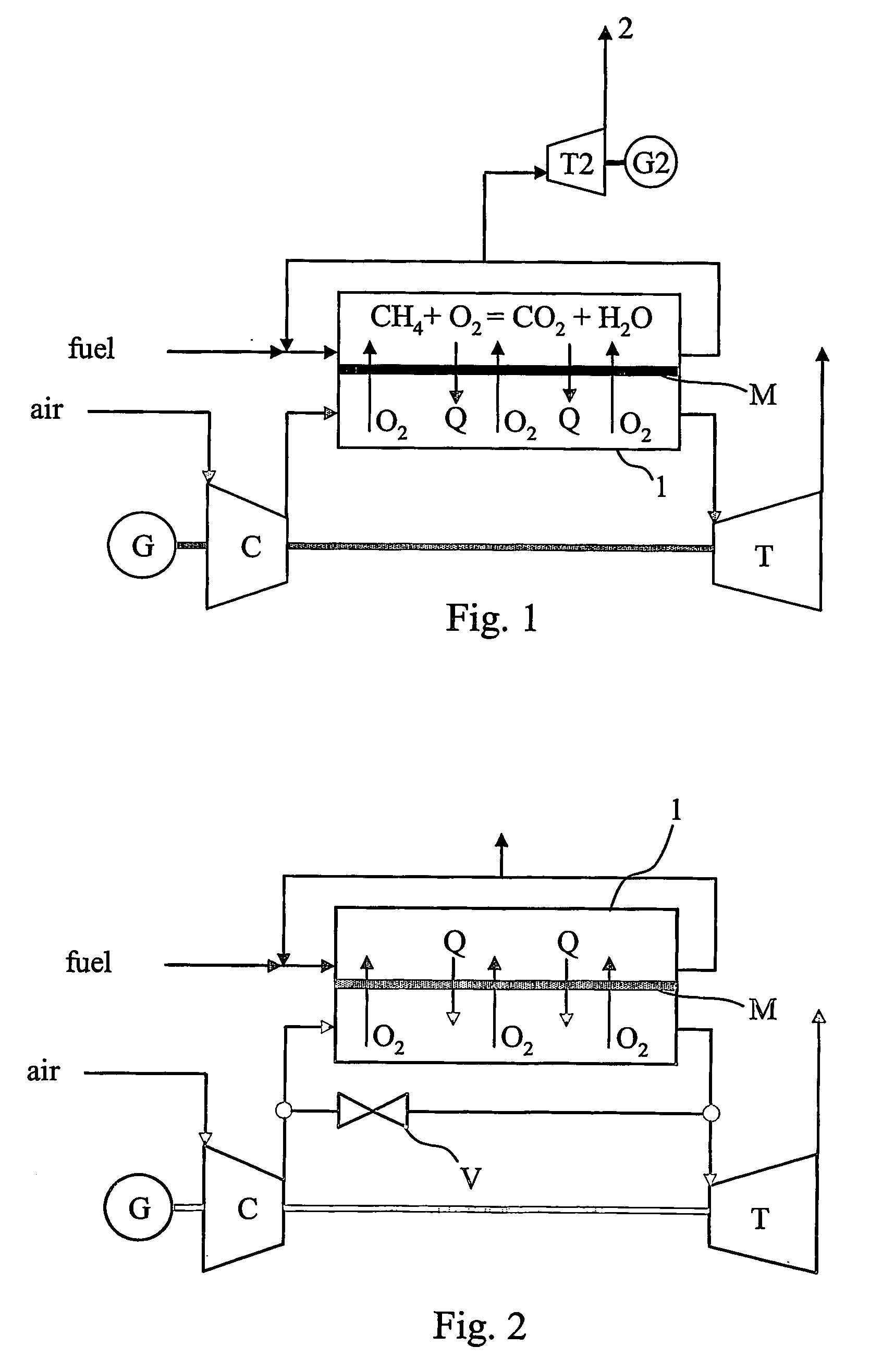
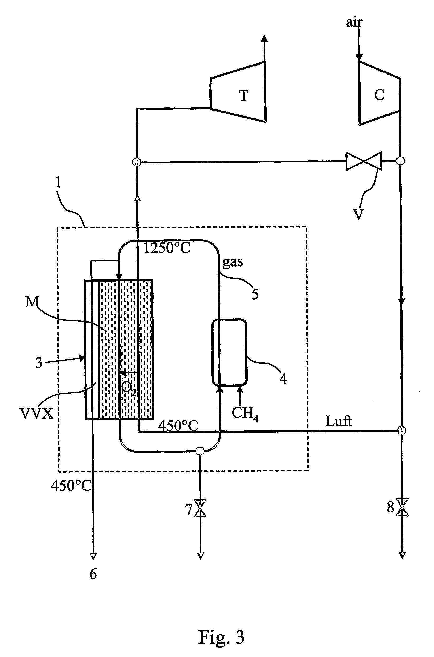
[0018] The arrangement for controlling the plant is shown in schematic form in FIG. 2. In the said figure C represents a compressor for compressing air, which after compression is delivered at increased pressure and higher temperature to an MCM reactor 1 according to the prior art. In the reactor 1 a fuel, in this case methane gas, is burned. The reactor comprises a heat exchanger, which gives off heat from the sweep circuit in the reactor to the air in the air circuit via the membrane M, which divides the reactor into a sweep circuit side and an air circuit side. The temperature of the air is thereby increased to around 1250° C. This heated air drives the gas turbine T. In order to be able to control the plant reliably ...


PUM


Abstract

A method for producing, on an SiC substrate, SiC homoepitaxial layers of the same polytype as the substrate. The layers are grown on a surface of the SiC substrate, wherein the surface is inclined relative to the (0001) basal plane at an angle higher than 0.1 degree but less than 1 degree. An homoepitaxial growth is started by forming a boundary layer with a thickness up to 1 μm.

Description

TECHNICAL FIELD [0001] The invention relates to a gas turbine in which combustion of a fuel takes place in a slow reactor, that is to say a reactor which cannot be rapidly controlled in the event of load fluctuations, for example by controlling the fuel supply. The invention relates in particular to an arrangement and a method for controlling a gas turbine in different operating situations occurring in the use of such a reactor. PRIOR ART [0002] A special gas turbine-based power generating process is proposed using a concept known by the abbreviation AZEP (Advanced Zero Emissions Power Plant). This process represents a cost-effective way of reducing local and global emissions. The innovative cycle on which the process is based makes it possible to reduce the carbon dioxide (CO2) emissions by 100%. A number of complementary additions allow conventional air-based gas turbine equipment to be used for power generation. The loss in plant efficiency is less than 2%. The key to achieving t...

Claims


Application Information

Patent Timeline
IPC IPC(8): F02C1/04B01D53/22F02C7/141F02C9/18
CPCB01D53/22F02C7/141F05D2270/303F23L2900/07001Y02E20/322F02C9/18Y02E20/32Y02T50/60
Inventor HAMRIN, STELLAN
Owner ALSTOM SWEDEN
Why Eureka
Try Eureka