
Apparatus for CPAP therapy

Inactive Publication Date: 2006-10-19
AEIOMED
View PDF13 Cites 50 Cited by
  • Summary
  • Abstract
  • Description
  • Claims
  • Application Information

AI Technical Summary

Benefits of technology

[0013] The present invention provides an apparatus for the supply of air for the treatment of sleep apnea. The apparatus of the present invention includes a fan unit. The fan unit includes a volute having an inlet and an outlet with an impeller rotatably supported within the volute. A motor is connected to the impeller such that the motor may impart power to the impeller thereby causing the impeller to rotate. The motor and fan unit are enclosed in an inner case of flexible foam plastics material. The inner case is configured to contain the motor and the fan unit, and the inner case is generally biased against the motor and the fan unit. The inner case is, in turn, contained within an intermediate case of rigid material. The intermediate case conforms to and is substantially filled by the inner case such that the inner case is generally biased against the intermediate case. Finally, the intermediate case is contained within an outer case of rigid material. The outer case surrounds the intermediate case. The outer case is generally set apart from the intermediate case so that there is a gap between the intermediate case and the outer case. The inner case, the intermediate case, and the outer case are all interconnected to form a blower housing in a manner that reduces the transmission of noise from the fan unit and from the motor to the external environment to the outer case.

Problems solved by technology

Currently available CPAP apparatus lack the capability of operating from battery power.

Method used


Image

  • Apparatus for CPAP therapy
  • Apparatus for CPAP therapy
  • Apparatus for CPAP therapy

Examples


Embodiment Construction

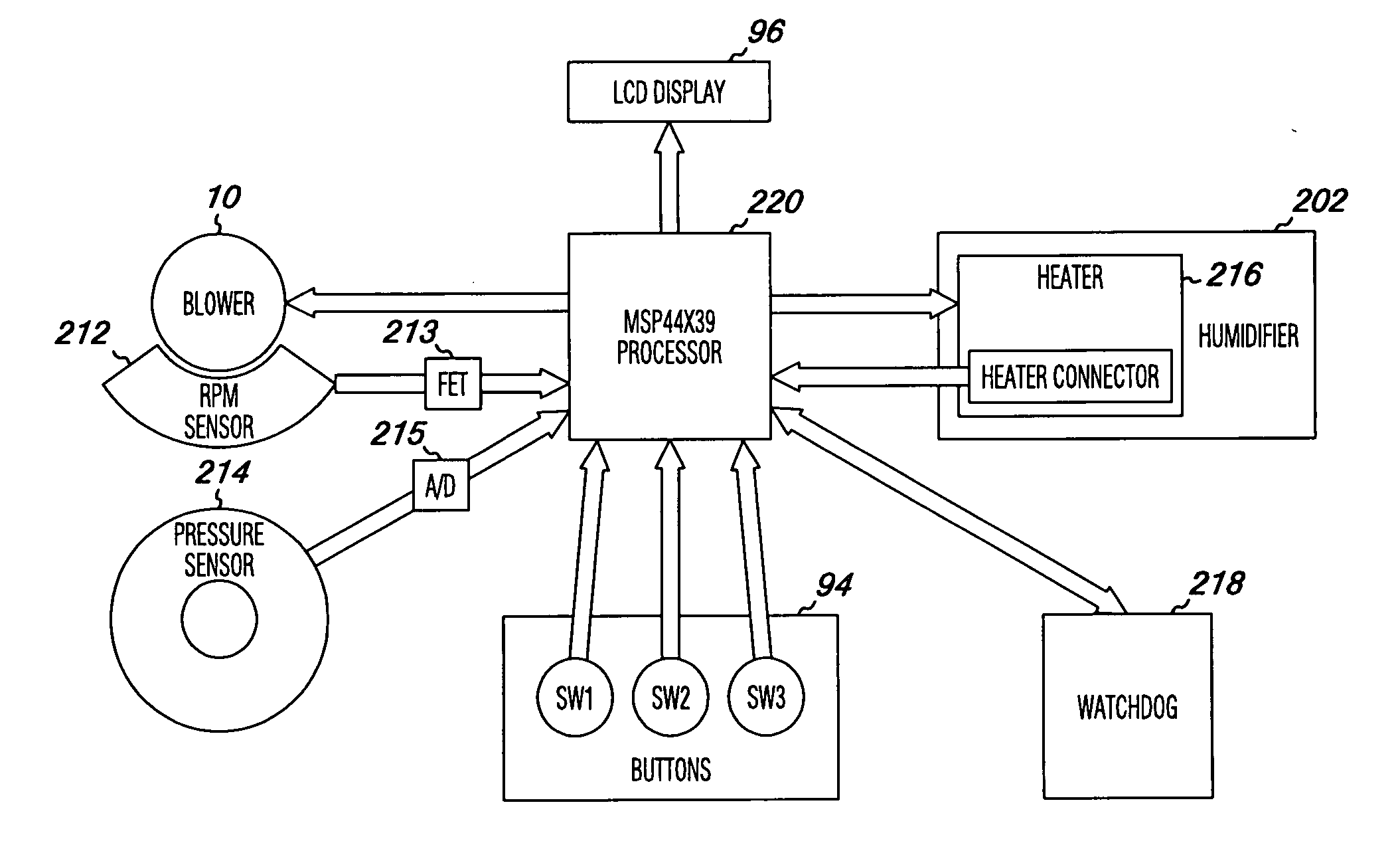
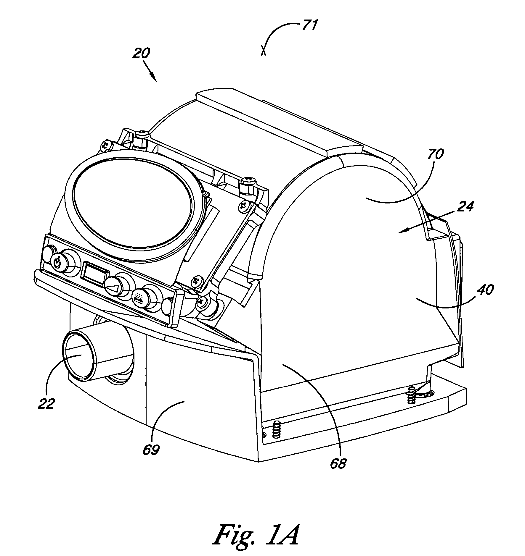
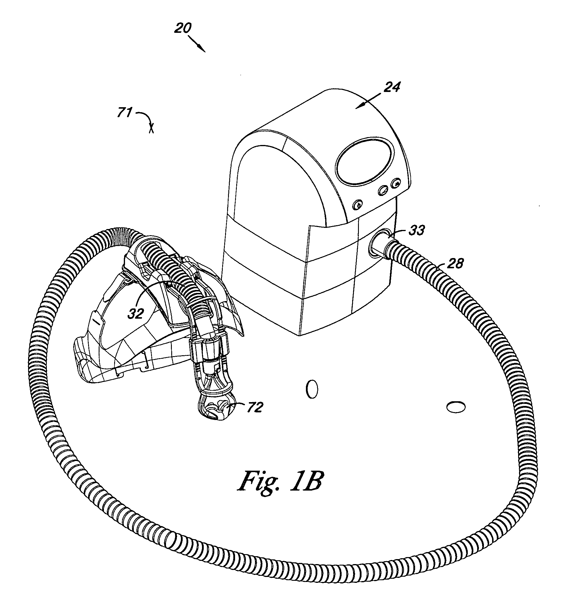
[0027] Apparatus 20 of the present invention may be used in the treatment of sleep apnea and other disorders. The Figures generally illustrate embodiments of apparatus 20 including aspects of the present inventions. The particular exemplary embodiments of the apparatus 20 illustrated in the Figures have been chosen for ease of explanation and understanding of various aspects of the present inventions. These illustrated embodiments are not meant to limit the scope of coverage but instead to assist in understanding the context of the language used in this specification and the appended claims. Accordingly, variations of apparatus 20 different from the illustrated embodiments may be encompassed by the appended claims.

[0028] The apparatus 20 of the present invention provides a fan unit 36 powered by an electric motor 56. A delivery tube 28 is connected to the fan unit 36 and to the face of the patient for delivery of pressurized air or other gasses to the patent through a patient inter...


PUM


Abstract

The present invention provides an apparatus for the supply of air for the treatment of sleep apnea. The apparatus of the present invention includes a motor and a fan unit. The motor and fan unit are enclosed in an inner case of flexible foam plastics material. The inner case is configured to contain the motor and the fan unit, and the inner case 48 is generally biased against the motor and the fan unit. The inner case is, in turn, contained within an intermediate case made of rigid material. The intermediate case conforms to and is substantially filled by the inner case such that the inner case is generally biased against the intermediate case. Finally, the intermediate case is contained within an outer case of rigid material. The outer case surrounds the intermediate case. The outer case is generally set apart from the intermediate case so that there is a gap between the intermediate case and the outer case. The inner case, the intermediate case, and the outer case are all interconnected to form a blower housing in a manner that reduces the transmission of noise from the fan unit and from the motor to the external environment to the outer case. The apparatus may also include a humidifier in fluid communication with the volute outlet so as to impart humidity to compressed air or other gasses provided to the patient. The apparatus may include a microcontroller and may be powered by battery. The microcontroller may receive signals from a battery voltage sensor, the motor rate of rotation sensor, and a pressure sensor. The microprocessor may execute an algorithm directed to maintain a constant pressure over a range of battery voltages by regulation of the motor rate of rotation in response to the battery voltage signal and the pressure signal. The control algorithm in the microcontroller may also be arranged to adjust a duty cycle of a heater in the humidifier to adjust the level of humidification provided by the humidifier.

Description

CROSS-REFERENCE TO RELATED APPLICATIONS [0001] This application claims the benefit of the filing date of U.S. Provisional Patent Application Ser. No. 60 / 667,797 filed Apr. 2, 2005, which is hereby incorporated herein in its entirety by reference.BACKGROUND OF THE INVENTION [0002] 1. Field of the Invention [0003] The present invention relates to medical devices, and, more particularly to apparatus for providing compressed air or other gas or gas mixtures e.g. for use in continuous positive airway pressure [CPAP] therapy and the treatment of sleep apnea. [0004] 2. Description of the Related Art [0005] It is known that applying a continuous positive airway pressure (CPAP) in the range of 4.5-10 cm water to a patient by way of the nose may prevent upper airway occlusion during sleep. CPAP apparatus has become the apparatus of choice for the treatment of chronic sleep apnea, chronic pulmonary obstruction and snoring. Many CPAP apparatus are now available. [0006] A typical CPAP apparatus ...

Claims


Application Information

Patent Timeline
IPC IPC(8): A61M16/00F24F3/14A62B7/00A61M15/00
CPCA61M16/0057A61M16/16A61M2016/0021A61M16/109A61M2205/42A61M2205/8212A61M16/0069A61M2205/3365
Inventor DOUGHERTY, TIMOTHY R.BASER, JOSEPH A.PETERSON, STEVEN J.ROMAN, THOMAS A.JOHNSON, PAUL H.
Owner AEIOMED
Learn More