Exposure apparatus and device manufacturing method

a technology of exposure apparatus and manufacturing method, which is applied in the direction of photomechanical apparatus, instruments, printing, etc., can solve the problems of rusting surrounding mechanical parts, insufficient focus margin during exposure operation, and inability to recover liquid, etc., and achieve high exposure accuracy.

Active Publication Date: 2006-10-19
NIKON CORP +1
View PDF99 Cites 378 Cited by
  • Summary
  • Abstract
  • Description
  • Claims
  • Application Information

AI Technical Summary

Benefits of technology

[0013] In accordance with the present invention, since the first recovery port is disposed further from the projection area than the supply port, and the second recovery port is disposed further from the projection area than the first recovery port, even if all of the liquid on the substrate cannot be recovered through the first recovery port, it is possible to recover the remaining liquid which cannot be recovered through the first recovery port, through the second recovery port. Therefore, it is possible to prevent exposure accuracy from deteriorating due to flowing out of the liquid.
[0015] In accordance with the present invention, since the porous member is disposed inside the recovery port, it is possible to prevent the occurrence of loud noise and vibration when the liquid on the substrate is recovered. Therefore, it is possible to prevent exposure accuracy from deteriorating due to the vibration or the like.
[0017] In accordance with the present invention, since the capillary tube member is disposed inside the recovery port of the liquid recovery device, it is possible to prevent loud noise and vibration from occurring when the liquid on the substrate is recovered. Therefore, it is possible to prevent exposure accuracy from deteriorating due to the vibration or the like.
[0019] In accordance with the present invention, since at least one of the quantity of the liquid supplied onto the substrate and the quantity of the liquid recovered from above the substrate is controlled, it is possible to recover only the liquid through the recovery port, and it is possible to prevent the occurrence of noise and vibration. Therefore, it is possible to prevent exposure accuracy from deteriorating due to the vibration or the like.
[0021] In accordance with the present invention, since the end portion of the liquid immersion area is detected, and then, for example, the quantity of the liquid supplied and / or the quantity of the liquid recovered are controlled based on the detection, it is possible to prevent spreading of the liquid immersion area and flowing out of the liquid.
[0023] In accordance with the present invention, it is possible to perform exposing while maintaining exposure accuracy high.

Problems solved by technology

If the depth of focus δ becomes too narrow, it becomes difficult to make the substrate surface coincide with the image plane of the projection optical system, and thus there occurs the possibility that the focus margin during the exposure operation will be insufficient.
Specially, if the liquid cannot be recovered smoothly, the remaining liquid which cannot be recovered flows out, and surrounding mechanical parts rust.
Therefore, various measuring operations relative to the exposing process may be affected.
As a result, exposure accuracy is lowered.
In addition, if a liquid supply device and / or a recovery device vibrate, the pattern image projected onto the substrate may deteriorate due to the vibration, and a measuring error of the interferometer which monitors the position of the substrate stage holding the substrate may be caused.

Method used


Image

  • Exposure apparatus and device manufacturing method
  • Exposure apparatus and device manufacturing method
  • Exposure apparatus and device manufacturing method

Examples


first embodiment

[0040] The following explains an exposure apparatus of the present invention referring to the figures.

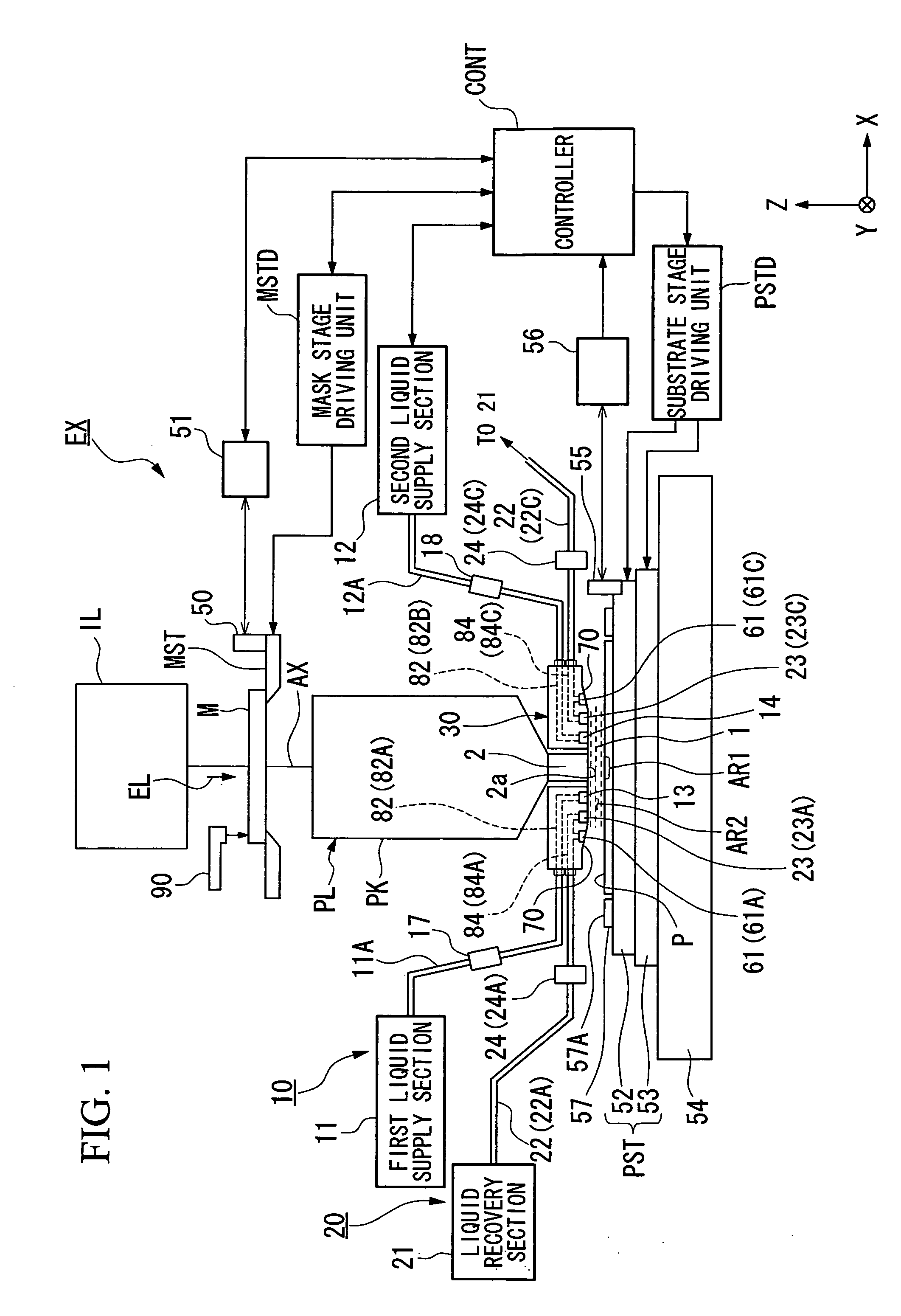
[0041]FIG. 1 is a general arrangement diagram showing the exposure apparatus of this embodiment. In FIG. 1, the exposure apparatus EX includes: a mask stage MST which holds a mask M; a substrate stage PST which holds a substrate P; an illumination optical system IL which illuminates the mask M held on the mask stage MST with exposure light EL; a projection optical system PL which projection-exposes a pattern image of the mask M illuminated by the exposure light onto the substrate P held on the substrate stage PST; and a controller CONT which collectively controls overall operations of the exposure apparatus EX.

[0042] The exposure apparatus EX of this embodiment is a liquid immersion exposure apparatus applying a liquid immersion method, in order to increase resolution by actually shortening the exposure wavelength, and to actually increase the depth of focus. This exposure apparatu...

second embodiment

[0102] The following explains an exposure apparatus of the present invention. In the following explanation, the same or equivalent components as in the embodiment described above are given the same reference numerals, and corresponding descriptions thereof are simplified or omitted.

[0103]FIG. 10 is a cross-sectional view of the passage forming member 30, and FIG. 11 is a view showing the positional relationship between the supply ports and the recovery ports, and the projection area AR1. This embodiment is explained on the basis in which the liquid recovery device 20 is not provided with the outside recovery ports (61), and is provided with only the recovery ports (inside recovery ports) 23.

[0104] In this embodiment, particularly, porous members 90 are respectively disposed inside the recovery ports 23. As shown in FIG. 10 and FIG. 11, the porous members 90 are arranged so as to fill up inside the recovery passages 84 formed in the passage forming member 30. As the porous members 9...

third embodiment

[0107] The following explains an exposure apparatus of the present invention referring to FIG. 12 and FIG. 13. In this embodiment, particularly, assemblies of capillary tubes 91 are respectively disposed inside the recovery ports 23. As shown in FIG. 12 and FIG. 13, the assemblies of capillary tubes 91 are disposed inside the recovery ports 23. The capillary tubes 91 are arranged so that the longitudinal directions thereof coincide with the recovery passage 84. The assembly of capillary tubes 91 divides the recovery port 23 into a plurality of passages. In this embodiment, as shown in FIG. 12, the capillary tubes 91 are disposed inside one part of the recovery passage 84, which extends from the recovery port 23 in the vertical direction. Further, as shown in FIG. 13, the capillary tubes 91 are arranged in two rows along the slit length direction of the recovery port 23.

[0108] For example, the capillary tubes 91 are made of glass, metal such as copper, synthetic resin, rubber or the ...


PUM

PropertyMeasurementUnit
depth of focusaaaaaaaaaa
refractive indexaaaaaaaaaa

Abstract

An exposure apparatus exposes a substrate by projecting a pattern image onto the substrate via a projection optical system and a liquid. The exposure apparatus includes a liquid supply device which supplies liquid onto the substrate from above the substrate through a first and second supply ports disposed in a vicinity of a projection area onto which the pattern image is projected, and a liquid recovery device which recovers liquid on the substrate from above the substrate through an inside recovery port disposed outside the first and second supply ports and an outside the second recovery port disposed outside the inside recovery port.

Description

CROSS-REFERENCE TO RELATED APPLICATIONS [0001] Priority is claimed on Japanese Patent Application No. 2003-328997, filed Sep. 19, 2003, the content of which is incorporated herein by reference. BACKGROUND OF THE INVENTION [0002] 1. Field of the Invention [0003] The present invention relates to an exposure apparatus and a device manufacturing method which performs exposure by irradiating a substrate with exposure light via a projection optical system and liquid. [0004] 2. Description of Related Art [0005] Semiconductor devices and liquid crystal displaying devices are manufactured by transferring a pattern formed on a mask onto a photosensitive substrate, in other words, through a photolithography technique. An exposure apparatus which is used in the photolithography processing, includes a mask stage which holds a mask, and a substrate stage which holds a substrate. The exposure apparatus transfers the mask pattern onto the substrate via a projection optical system, while successivel...

Claims


Application Information

Patent Timeline
Patent Type & Authority Applications(United States)
IPC IPC(8): C23F1/00H01L21/306G03F7/20H01L21/027
CPCG03F7/70341
Inventor NAGASAKA, HIROYUKIYAMAMOTO, TAROHIRAKAWA, OSAMU
Owner NIKON CORP
Why Eureka
Try Eureka