Disk brake caliper having re-enforcing bridge

a brake caliper and disk brake technology, applied in the direction of brake types, mechanical devices, axially engaging brakes, etc., can solve the problems of low structural stiffness and low load capacity of low strength calipers, and achieve the effects of low strength, low load capacity and reduced weigh

Inactive Publication Date: 2006-10-19
GILLILAND WARREN
View PDF5 Cites 11 Cited by
  • Summary
  • Abstract
  • Description
  • Claims
  • Application Information

AI Technical Summary

Benefits of technology

[0011] The bridge, as such, provides structural support for the caliper housing members. The caliper housing is commonly made of low tensile strength materials in order to reduce weight, as the weight of the caliper, which tends to be relatively heavy, can affect the operation and suspension of the chassis. However, a low strength caliper will have low load capacity and low structural stiffness. The C-bridge provides structural rigidity by using high tensile strength materials, creating a “bending moment” situation, which improves support to the low strength caliper housing members. By using high strength materials only where needed, the strength of the caliper can be maximized while still minimizing weight.
[0012] One key advantage of the present invention to be noted is the use of high tensile strength anchors (i.e. the downward turning arms) in between the pistons of the caliper, especially as assembled to the center portion of the caliper. The use of high strength downward turning arms allows for a stronger bridge design to reduce deflection.
[0013] Structurally, the first and second members each have at least one channel provided therein respectively for receiving the anchor members of the bridge, and at least one hole formed therein respectively in substantial alignment with the channels. The bridge has at least two holes formed in the anchor members. The bridge anchor members are capable of fitting flush in the channels of the first and second members, such that the holes in the bridge anchor members coaxially align with the holes in the first and second members. A securing means, such as a bolt, capable of passing through the holes in the first and second caliper housing members and engaging the holes in the bridge, acts to secure the first member and second member to the bridge.

Problems solved by technology

However, a low strength caliper will have low load capacity and low structural stiffness.

Method used


Image

  • Disk brake caliper having re-enforcing bridge
  • Disk brake caliper having re-enforcing bridge
  • Disk brake caliper having re-enforcing bridge

Examples


Embodiment Construction

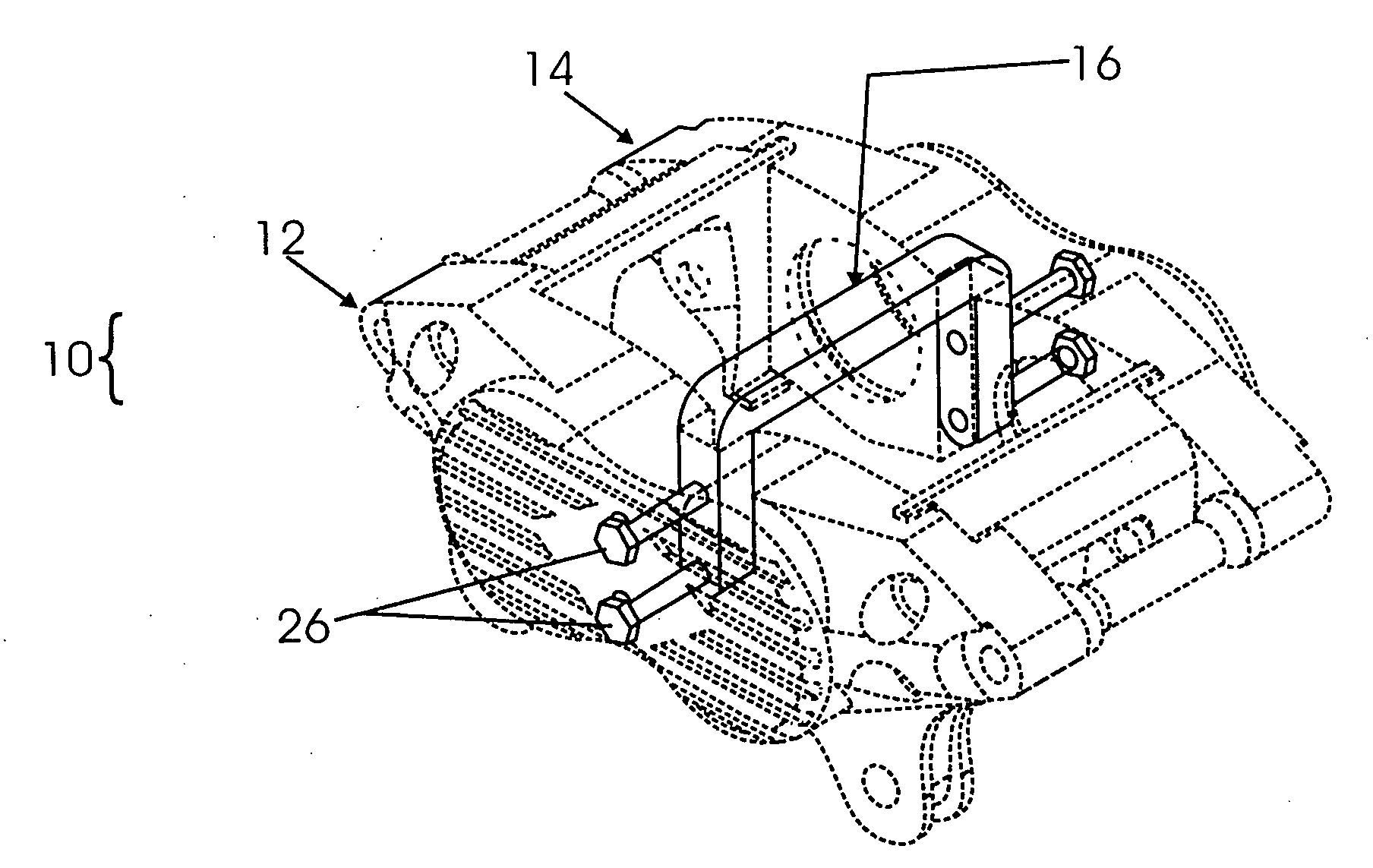
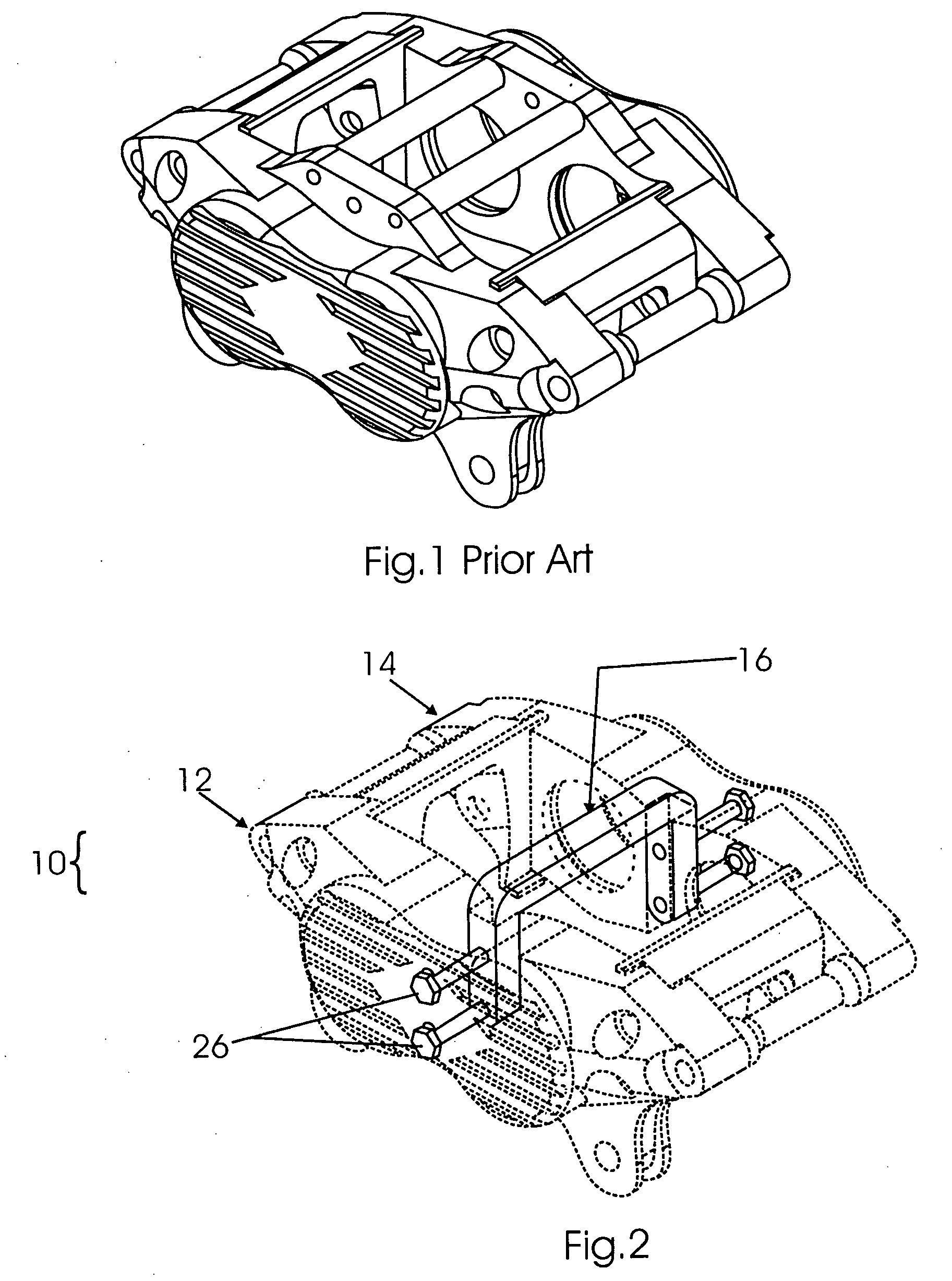
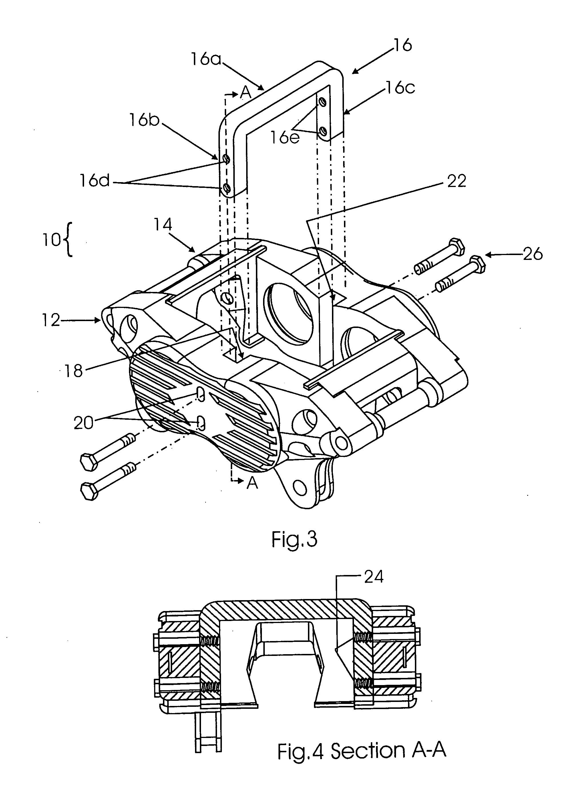
[0021] A preferred embodiment of a brake caliper is shown in FIGS. 2 and 3. Referring to FIG. 2, the brake caliper 10 has first member 12 and second member 14 straddling the rotor (not shown), with first and second members 12, 14 connected by a bridge 16. FIG. 2 shows brake caliper 10 with bridge 16 connected to first and second members 12, 14. FIG. 3 shows a partially exploded view of brake caliper 10 with bridge 16 unconnected to first and second members 12, 14. It is to be noted that although FIGS. 2 and 3 show a C-section bridge 16, the bridge can take a variety of form and shape that incorporate the basic combination of cross member and associated anchors.

[0022] Referring to FIG. 3, C-section bridge 16 is generally comprised of a cross member 16a and associated anchor arms 16b and 16c. The C-section bridge 16 has at least one hole 16d in arm 16b and at least one hole 16e in arm 16c. The first member 12 has at least one channel 18 provided therein for receiving arm 16b of C-sec...


PUM


Abstract

A brake apparatus includes a caliper with two housing members secured together by a C-section bridge. The housing members straddle a rotor, so as to be able to urge one or more pistons disposed therein to apply brake pads against the rotor, thereby effectuating a braking force on the rotor. The C-section bridge provides support for the members and reduces the clamshell effect generated by application of the breaking force.

Description

BACKGROUND OF THE INVENTION [0001] This invention relates generally to a vehicular disk brake apparatus and more particularly to the brake caliper thereof, which has a reinforced bridge for reducing load. [0002] In general, a vehicular or automotive brake operates on a hydraulic system, in which the depression of a brake pedal causes a plunger in the master cylinder to push hydraulic fluid to a braking unit at the wheels. A disk brake is one kind of braking unit. In a conventional opposed caliper disk brake, a fixed caliper straddles a rotor, which is attached to the wheel. In a floating caliper disk brake, the caliper urges piston or pistons on one side of the rotor to apply a pad, while at the same time pushing the caliper housing away from the rotor, drawing the outboard pad up to the rotor. In either case, when fluid from the master cylinder is introduced into the caliper, it urges one or more pistons in the caliper to apply brake pad(s) against the rotor, thereby effectuating a...

Claims


Application Information

Patent Timeline
Patent Type & Authority Applications(United States)
IPC IPC(8): F16D55/00
CPCF16D2055/0016F16D55/228
Inventor GILLILAND, WARREN
Owner GILLILAND WARREN
Why Eureka
Try Eureka