Supercharge Your Innovation With Domain-Expert AI Agents!

Control circuit for command signals of clock generator

a control circuit and clock generator technology, applied in the direction of generating/distributing signals, instruments, pulse techniques, etc., can solve the problem of increasing the cost of motherboard manufacture, and achieve the effect of reasonable cos

Inactive Publication Date: 2006-10-19
HONG FU JIN PRECISION IND (SHENZHEN) CO LTD +1
View PDF8 Cites 8 Cited by
  • Summary
  • Abstract
  • Description
  • Claims
  • Application Information

AI Technical Summary

Benefits of technology

[0008] It is of advantage that employing a diode as a switch to replace the two transistors of the prior art can be mass produced at a reasonable cost.

Problems solved by technology

However, employing the two transistors to control the command signals of the clock generator increases the cost of the manufacture of the motherboard.

Method used


Image

  • Control circuit for command signals of clock generator
  • Control circuit for command signals of clock generator
  • Control circuit for command signals of clock generator

Examples


Embodiment Construction

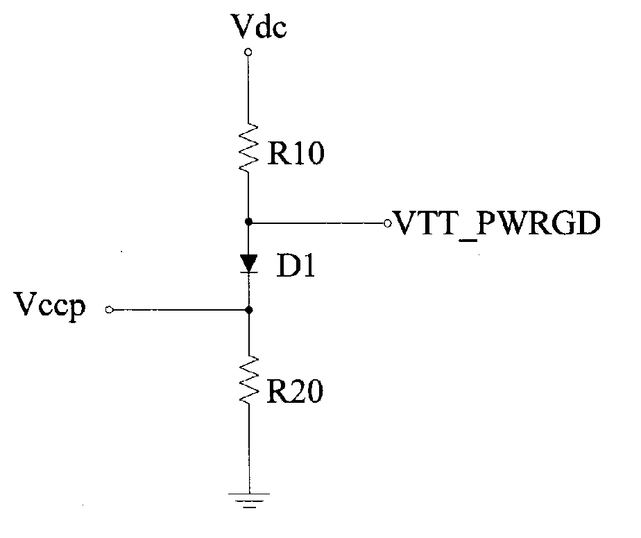
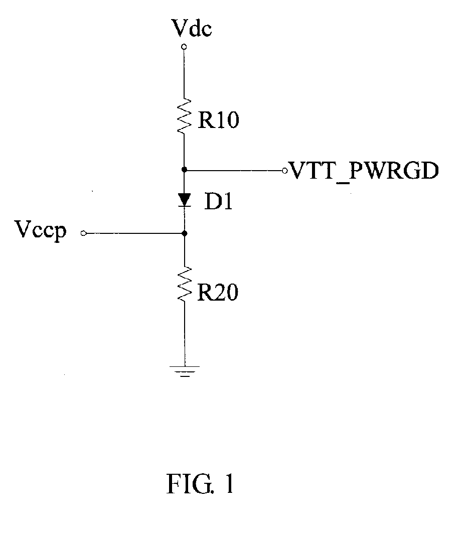
[0013] Referring to FIG. 1, a control circuit for command signals of a clock generator includes a diode D1, a first resistor R10, a second resistor R20, a control end Vccp, a power supply end Vdc, and an output end VTT_PWRGD. The first resistor R1, the diode D1, and the second resistor R2 are connected in series between the power supply end Vdc and the ground. An anode of the diode D1 is connected to the first resistor R1, and a cathode of the diode D1 is connected to the second resistor R20. The control end Vccp is connected at a node between the diode D1 and the second resistor R20. The output end VTT_PWRGD is connected to a node between the first resistor R10 and the diode D1. A voltage of the power supply end Vdc is 3.3V.

[0014] When the voltage of the control end Vccp is at a high level, the diode D1 is turned off, the voltage at the output end VTT_PWRGD is at a high level to enable the clock generator to generate clock signals; when the voltage of the control end Vccp is at a ...


PUM


Abstract

A control circuit for command signals of a clock generator includes a power supply end, an output end, a control end, a diode, a first resistor and a second resistor. The first resistor, the diode, and the second resistor are connected in series between the power supply end and the ground. The diode has an anode connected to the first resistor and a cathode connected to the second resistor. The control end is connected to a node between the diode and the second resistor; the output end is connected to a node between the diode and the first resistor. The output end outputs the command signals to the clock generator.

Description

DESCRIPTION [0001] 1. Field of the Invention [0002] The present invention relates in general to a control circuit of command signals, and more particular to a control circuit of command signals of a clock generator. [0003] 2. Description of Related Art [0004] A clock generator mounted on a motherboard of a computer is used to determine the CPU, PCI, and system bus speeds. The clock generator is controlled by command signals from a control circuit. If all of the voltages at the planar connector from the power supply are within a predetermined tolerance level, i.e. within specification, the power good (PG) signal goes high thereby causing the clock generator to generate clock signals to a computer system. [0005]FIG. 3 illustrates a conventional control circuit for command signals of a clock generator. The control circuit includes two transistors Q1 and Q2. A base of the transistor Q1 is connected via a resistor R3 to a control end Vccp, a collector of the transistor Q1 is coupled to a...

Claims


Application Information

Patent Timeline
IPC IPC(8): G11C5/14
CPCG11C7/22H03K17/74G11C7/222
Inventor HUANG, YONG-ZHAOJIANG, WULI, YUNYOU, YONG-XING
Owner HONG FU JIN PRECISION IND (SHENZHEN) CO LTD
Features
  • R&D
  • Intellectual Property
  • Life Sciences
  • Materials
  • Tech Scout
  • Unparalleled Data Quality
  • Higher Quality Content
  • 60% Fewer Hallucinations
Learn More