Active-matrix display panel

a display panel and active matrix technology, applied in non-linear optics, instruments, optics, etc., can solve the problems of increasing the difficulty of layout arrangement of fanout circuitry, and achieve the effect of increasing the layout flexibility of fanout circuitry

Inactive Publication Date: 2006-10-19
PRIME VIEW INTRNAT
View PDF3 Cites 23 Cited by
  • Summary
  • Abstract
  • Description
  • Claims
  • Application Information

AI Technical Summary

Benefits of technology

[0009] The present invention is directed to provide an active-matrix display panel which uses a multi-layered routing structure to increase the layout flexibility of the fanout circuitry on the peripheral region.

Problems solved by technology

The layout arrangement of the fanout circuitry will become more and more difficult when the number of fanout traces is increased due to the user-side request of higher display resolution.
Therefore, how to effectively utilize the limited peripheral region with the variation of the structure to increase the layout flexibility of the fanout circuitry is an issue to be solved urgently.

Method used


Image

  • Active-matrix display panel
  • Active-matrix display panel
  • Active-matrix display panel

Examples


Embodiment Construction

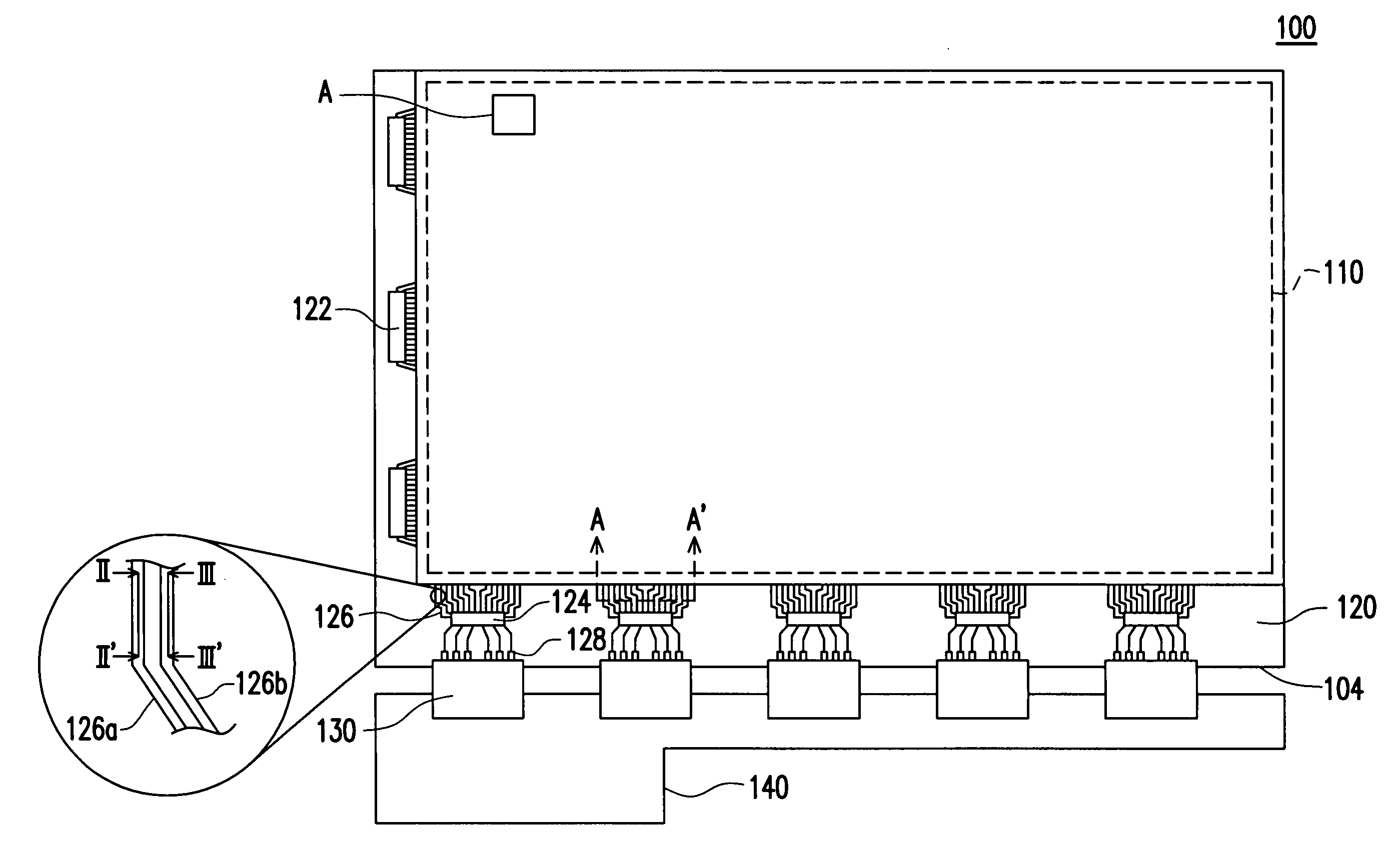
[0025] Typically, active-matrix display driving method can be applied to various display technologies, such as Liquid Crystal Display (LCD), Organic Electro-Luminescence Display (OEL), Plasma Display Panel (PDP), Field Emission Display (FED), carbon nanotubes (CNT) and E-ink display, etc. The structure of each kind of display panel includes a display area where the image is displayed, and a peripheral region where driving circuits and other related circuitry are disposed to drive the components within the display area.

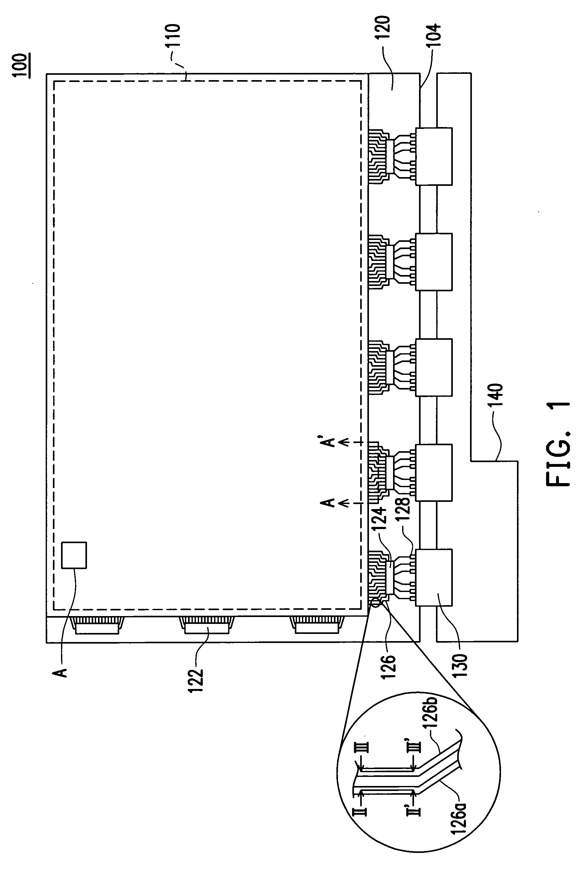
[0026]FIG. 1 is a top view of the active-matrix display panel in an embodiment of the present invention, in which an active-matrix LCD panel is illustrated as an example. However, the present invention can also be applied to other types of active-matrix display panels without being limited to the application to LCDs.

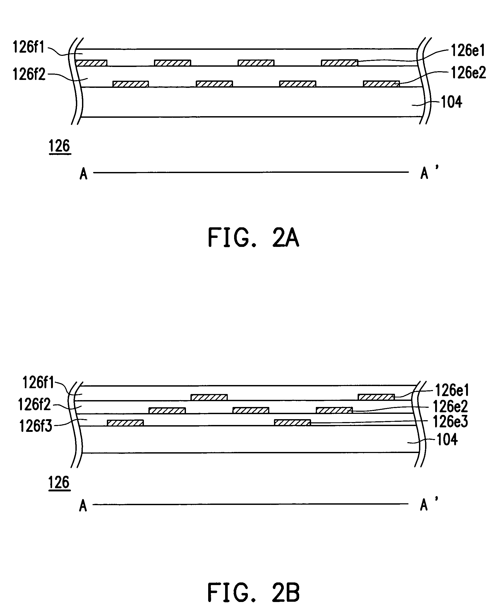
[0027] With reference to FIG. 1, the active-matrix display panel 100 of the present invention includes a display area 110, a peripheral region 120 and a ...


PUM

PropertyMeasurementUnit
conductiveaaaaaaaaaa
weightaaaaaaaaaa
areaaaaaaaaaaa

Abstract

An active-matrix display panel including a display area, a peripheral region and a fanout circuitry is provided. The peripheral region is connected with at least one side of the display area. The fanout circuitry is arranged on the peripheral region and is a multi-layered routing structure. By using the multi-layered routing structure aforementioned, the layout flexibility is improved significantly.

Description

CROSS-REFERENCE TO RELATED APPLICATION [0001] This application claims the priority benefit of Taiwan application serial no. 94112346, filed on Apr. 19, 2005. All disclosure of the Taiwan application is incorporated herein by reference. BACKGROUND OF THE INVENTION [0002] 1. Field of Invention [0003] The present invention relates to an active-matrix display panel, more particularly, to an active-matrix display panel having a multi-layered fanout circuitry. [0004] 2. Description of Related Art [0005] Following the rapid developments of the display industry, the flat-panel display is required to provide higher quality. As the image resolution of the display is constantly improving, the module size of the product becomes smaller and the weight of the product becomes lighter. The corresponding packaging technology was evolved from the Chip On Board (COB) technology to the Tape Automated Bonding (TAB) technology, and is further evolved to the present fine pitch Chip On Glass (COG) technolo...

Claims


Application Information

Patent Timeline
Patent Type & Authority Applications(United States)
IPC IPC(8): G02F1/1345
CPCG02F2001/13629G02F1/1345G02F1/13629
Inventor LIN, TUNG-LIANGHSU, YU-CHENLIU, CHUAN-FENGKUO, CHIA-HAOTENG, YU-CHUN
Owner PRIME VIEW INTRNAT
Why Eureka
Try Eureka