Ion generator

a generator and ion technology, applied in the field of ion generators, can solve the problems of difficult to make the ion generator compact and light, destabilizing the ion balance, and large coupled capacitance of the discharge needle,

Active Publication Date: 2006-10-19
SHISHIDO SEIELECTRIC
View PDF6 Cites 41 Cited by
  • Summary
  • Abstract
  • Description
  • Claims
  • Application Information

AI Technical Summary

Benefits of technology

[0012] To achieve the foregoing object, the inventors pertaining to the present application conducted various studies and experiments. As a result, the inventors found that, in an ion generator provided with a high frequency AC power source equipped with a piezoelectric transformer, even if the discharge needle was capacitance-coupled with the high voltage output line of the high frequency AC power source, an AC corona discharge could be satisfactorily generated from the discharge needle while sufficiently reducing the drop of the voltage from the high voltage output line from the high frequency AC power source to the discharge needle and that at the same time the capacitance coupling could serve to balance the quantities of the positive and negative air ions and to stabilize that balance compared with the conventional high frequency ion generator, thereby improving the ion balance.
[0026] This makes it possible for the cylindrical insulating member to readily constitute an insulator to cover the annular opposed electrode and to uniformize the positional relationship between the cylindrical insulating member and the discharge needles for every discharge needle. In this case incidentally, the ions generated in the cylindrical insulator can be delivered out of the cylindrical insulator by supplying air into the cylindrical insulator in the axial direction thereof.

Problems solved by technology

It is difficult here for the discharge needle to have a very large coupled capacitance because of structural constraints and the need to secure the effect to restrain the short-circuiting current, and the capacitance can be at most 10 pF or so for practical purposes.
However, since a wound-wire transformer is relatively large and heavy, this involves a problem of difficulty to make the ion generator compact and light.
However, in the conventional ion generator using a high frequency power source, the ion balance is often destabilized, and the requirement cannot be always fully satisfied.

Method used


Image

  • Ion generator
  • Ion generator
  • Ion generator

Examples


Embodiment Construction

[0028] A first mode for carrying out the present invention will be described below with reference to FIG. 1 through FIG. 4.

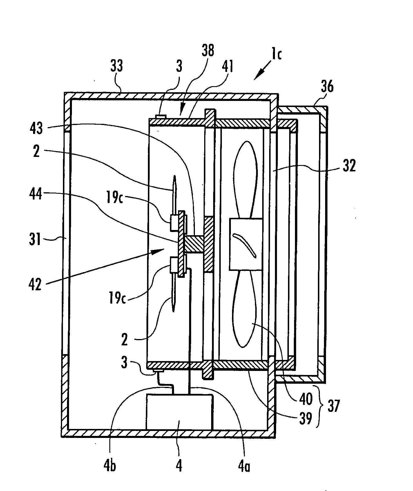
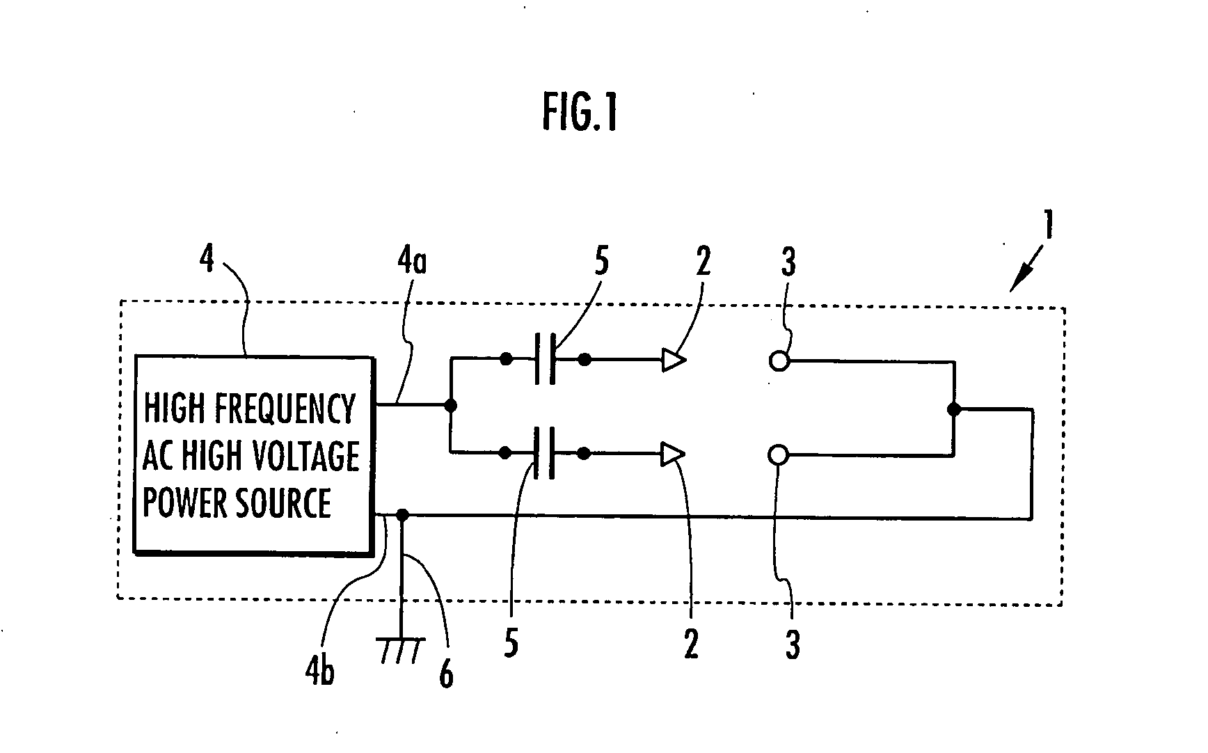
[0029] Referring to FIG. 1, an ion generator 1 in the first mode for carrying out the invention comprises discharge needles 2, opposed electrodes 3 opposite the discharge needles 2, a high frequency AC high voltage power source 4 and condenser units (capacitance units) 5 as its electrical circuit configuration.

[0030] Although two each of the discharge needles 2 and the opposed electrodes 3 are shown in FIG. 1, at least one each could suffice. The number of the discharge needles 2 and that of the opposed electrodes 3 need not be equal, but one opposed electrode 3 may be disposed opposite a plurality of discharge needles 2.

[0031] An output cable (high voltage output line) 4a of the high frequency AC high voltage power source 4 is connected to the discharge needles 2 via the condenser units 5. The opposed electrodes 3 are connected to a return cable 4b of the hi...


PUM


Abstract

In an ion generator comprising a discharge needle 2, an opposed electrode 3 opposite the discharge needle 2 and an AC high voltage power source 4, for generating positive and negative air ions by giving rise to a corona discharge when a high voltage is applied by the AC high voltage power source 4 between the discharge needle 2 and the opposed electrode 3, the AC high voltage power source 4 comprises a high frequency oscillator 7 and a piezoelectric transformer 9, and outputs a high frequency voltage. An insulator 5 is placed intervening between the high voltage output line 4a of the AC high voltage power source 4 and the discharge needle 2 to capacitance-couple them, and the discharge needle 2 is enabled to discharge electricity. Preferably, the surface of the opposed electrode 3 should be covered with an insulator. This enables the balance between positive and negative air ions and its stability to be improved while reducing the hardware configuration in size and weight.

Description

TECHNICAL FIELD [0001] The present invention relates to an ion generator which generates by corona discharge positive and negative air ions suitable for neutralizing the static electricity of and deelectrifying a charged object. BACKGROUND ART [0002] There is already known an ion generator which applies a high voltage from an AC high voltage source of the commercial frequency (50 or 60 Hz) between a discharge needle and an opposed electrode, generates a corona discharge from the discharge needle and ionizes air by that corona discharge (see Japanese Patent Application Laid-Open No. 8-288094 for instance). [0003] In an ion generator of this kind, positively charged air ions and negatively charged air ions are alternately generated by alternately applying an AC voltage to the discharge needle. And the ion generator of this kind, as it can neutralize the electric charges (static electricity) accumulated on the charged object with the generated positive and negative air ions, is general...

Claims


Application Information

Patent Timeline
Patent Type & Authority Applications(United States)
IPC IPC(8): H01H47/00H01T23/00
CPCH01T23/00H01T19/04
Inventor IZUMI, KENKICHISI, JIANMIN
Owner SHISHIDO SEIELECTRIC
Why Eureka
Try Eureka