Method for image intensity correction using extrapolation and adaptive smoothing

a technology of image intensity and extrapolation, applied in the field of image intensity correction, can solve the problems of inability to apply to previously acquired images, inability to modify the actual imaging procedure, and often suffer from non-uniformity of mri images,

Inactive Publication Date: 2006-10-19
INVIVO CORP
View PDF3 Cites 30 Cited by
  • Summary
  • Abstract
  • Description
  • Claims
  • Application Information

AI Technical Summary

Problems solved by technology

MRI images often suffer from non-uniformity that gives false image contrasts.
These methods require modifications to the actual imaging procedure and cannot be applied to previously acquired images.
Intensity inhomogeniety can hinder visualization of the entire image, and can also hinder automated image analysis, like segmentation.
Magnetic resonance imaging (MRI) can have this problem because of, for example, poor radio frequency (RF) coil uniformity, static field inhomogeniety, radio frequency penetration, gradient-driven eddy currents, and / or overall patient anatomy and position.
Phased array surface RF coils can improve the homogeneity but still suffer from non-uniformity, such as bright spots in the image.
However, an accurate sensitivity profile cannot be directly measured or calculated.
These methods require modifications to the actual imaging procedure and cannot be applied to previously acquired MR images.
While the N3 algorithm provides a genuinely automatic non-uniformity estimate, it still falls short at several levels.
Although trivial in most images, the foreground needs to be segmented from the background, thus making intensity correction difficult for regions of interest where the signal drops to noise level.
The necessarily iterative nature of the N3 method introduces biases caused by non-uniform noise levels in the iterative images that are additive and not multiplicative.
Segmentation based intensity correction methods have a tendency to generate piecewise constant images and typically do not handle bright spots effectively.
This means the estimated sensitivity profiles could be too smooth at regions closer to the coil, and hence it is difficult to get rid of the bright spots that are common in MRI with phased array coils.
These methods also exhibit the edge enhancement problem at the image boundary (between the image support, which is the region containing most of the signal strength, and holes, which is the region containing almost no signal strength, in the image).
This is because there is an inherent lack of information of sensitivity profile outside of the boundary.
Therefore, the filter generates errors near the boundary.
This does reduce the error but does not eliminate the problem, especially when the average is significantly different from the boundary intensity values.
This means the estimated sensitivity profiles could be too smooth at regions closer to the coil, and hence it is difficult to get rid of the bright spots that are common in MRI with surface coils.
But this assumption is generally not valid for MR images (D. A. G. Wicks, G. J. Barker, and P. S. Tofts, “Correction of intensity non-uniformity in MR images of any orientation,” Mag. Reson. Imag, vol.
One of the many issues that homomorphic filtering has is that it tends to underestimate the bias field at tissue / air boundaries.
However, the smoothing is non-adaptive; hence, it is difficult to balance the preservation of contrast and the removal of bright spots.
These methods typically always have the same problem at the image boundary.
Another problem of these those methods is that they treat all image pixels equally, which means the intensity correction map could be too smooth.
Accordingly, it is difficult to get rid of the hot spots, which are common in MRI with surface coils.

Method used


Image

  • Method for image intensity correction using extrapolation and adaptive smoothing
  • Method for image intensity correction using extrapolation and adaptive smoothing
  • Method for image intensity correction using extrapolation and adaptive smoothing

Examples


example 1

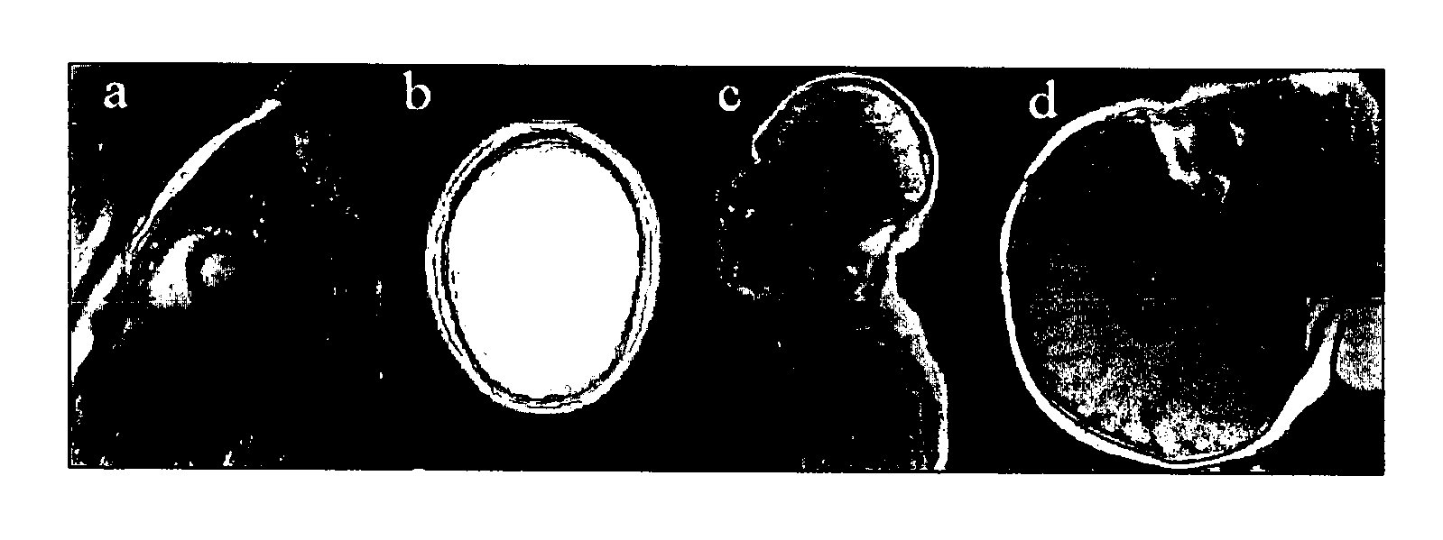
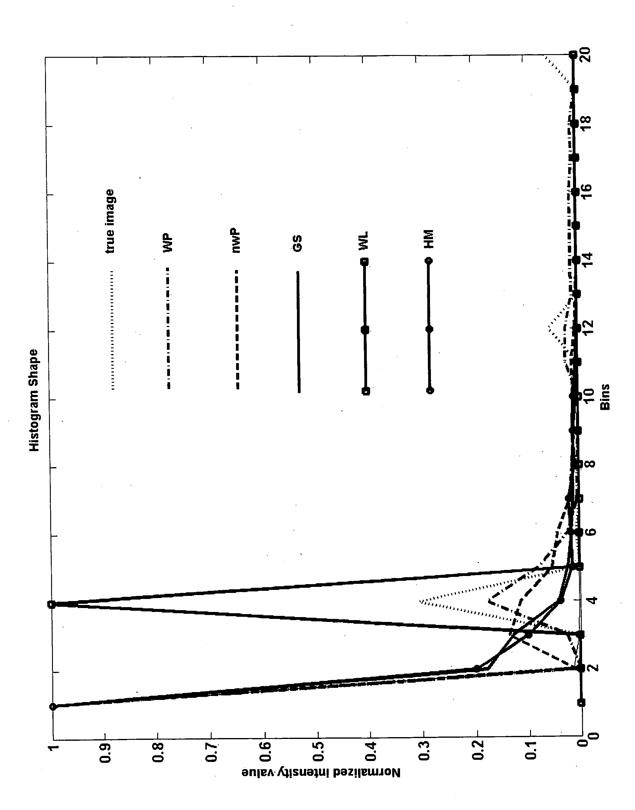
[0062] In this example, we evaluate an embodiment of the subject method by using both phantom and clinical data. For evaluation of accuracy, simulated phantom data was used. Histogram and correlation with true uniform image were used as criteria for accuracy. To test the stability, MRI images collected on different MRI systems (GE, SIEMENS, HITACHI) and for different organs (brain images, cardiac images, neurovascular images) were used. For comparison, the results using an embodiment of the subject method were compared with images corrected using Gaussian smoothing (M. S. Cohen, R. M. DuBois, and M. M. Zeineh, “Rapid and Effective Correction of RF Inhomogeneity for High Field Magnetic Resonance Imaging,” Human Brain Mapping, vol. 10, pp. 204 -211, 2000), wavelet based method (F.-H. Lin, Y.-J. Chen, J. W. Belliveau, and L. L. Wald, “Removing Signal Intensity Inhomogeneity from Surface Coil MRI Using Discrete Wavelet Transform and Wavelet Packet,” presented at Engineering in Medicine ...


PUM


Abstract

The subject invention pertains to a method of image intensity correction. The subject invention can utilize extrapolation for image intensity correction. The use of extrapolation can reduce the artifacts during intensity correction as compared to traditional methods of intensity correction. The extrapolation can be combined with, for example, homomorphic filtering methods, parametric estimation techniques, wavelet based method, and/or Gaussian smooth method, in order to reduce the artifacts generated by these methods and improve the quality of correction. The implementation of image extrapolation in accordance with a specific embodiment can utilize closest point method. The subject method can also use adaptive smoothing for image intensity correction. In an embodiment, the use of gradient weighted smoothing method can reduce, or eliminate, over-smoothing of bright spot regions. In a specific embodiment, the subject method can utilize gradient weighted partial differential equation (PDE) smoothing.

Description

CROSS-REFERENCE TO RELATED APPLICATION [0001] This application is a continuation-in-part of U.S. patent application Ser. No. 11 / 281,523, filed Nov. 16, 2005, and claims the benefit of U.S. Provisional Application Ser. No. 60 / 671,615, filed Apr. 15, 2005, both of which are hereby incorporated by reference herein in their entirety, including any figures, tables, or drawings.BACKGROUND OF INVENTION [0002] The subject invention relates generally to a method for image intensity correction. In various embodiments, the subject invention pertains to the use of extrapolation and / or adaptive smoothing. In a specific embodiment, the subject method can be applied to magnetic resonance imaging (MRI). [0003] MRI images often suffer from non-uniformity that gives false image contrasts. Therefore, intensity correction of the images often becomes important in order to interpret the image correctly. [0004] There are many approaches to intensity correction of images, such as MRI images. Non-retrospect...

Claims


Application Information

Patent Timeline
Patent Type & Authority Applications(United States)
IPC IPC(8): G06K9/40G06V10/30
CPCG01R33/5608G01R33/56563G01R33/5659G06T2207/30004G06T5/001G06T5/005G06K9/40G06V10/30
Inventor CHENG, HUHUANG, FENG
Owner INVIVO CORP
Why Eureka
Try Eureka