Control device of vehicular fuel cell system and related method

a fuel cell and control device technology, applied in climate sustainability, propulsion parts, process and machine control, etc., can solve problems such as incorrect discrimination, and achieve the effect of improving the fuel saving performance of a fuel cell powered vehicle and saving energy for warm-up

Active Publication Date: 2006-10-19
NISSAN MOTOR CO LTD
View PDF11 Cites 22 Cited by
  • Summary
  • Abstract
  • Description
  • Claims
  • Application Information

AI Technical Summary

Benefits of technology

[0005] The present invention has been completed upon such studies conducted by the present inventors and, specifically, has an object to provide a control device of a vehicular fuel cell system and its related method that enable time, needed before making judgment to find whether warm-up has been completed, to be minimized and energy required for warm-up to be saved for thereby improving fuel saving performance of a fuel cell powered vehicle.

Problems solved by technology

However, upon careful studies conducted by the present inventors, with such a vehicular fuel cell system, since the fuel cell stack is formed in a larger size than that of a domestic electric power supply with a view to supplying vehicle drive electric power with resultant increase in unevenness in temperature distribution between a stack central portion and a stack terminal portion, it is conceivable that depending upon conditions such as output of the fuel cell stack, required for ircumstance in an initial stage of start-up and at warm-up completion, it tends to e hard to correctly discriminate, based on only the temperature factor, to find hether the warm-up of the fuel cell stack has been completed.

Method used


Image

  • Control device of vehicular fuel cell system and related method
  • Control device of vehicular fuel cell system and related method
  • Control device of vehicular fuel cell system and related method

Examples


first embodiment

[0021] First, referring to FIGS. 1 to 7, a control device of a vehicular fuel cell system and its related method of a first embodiment according to the present invention are described below in detail.

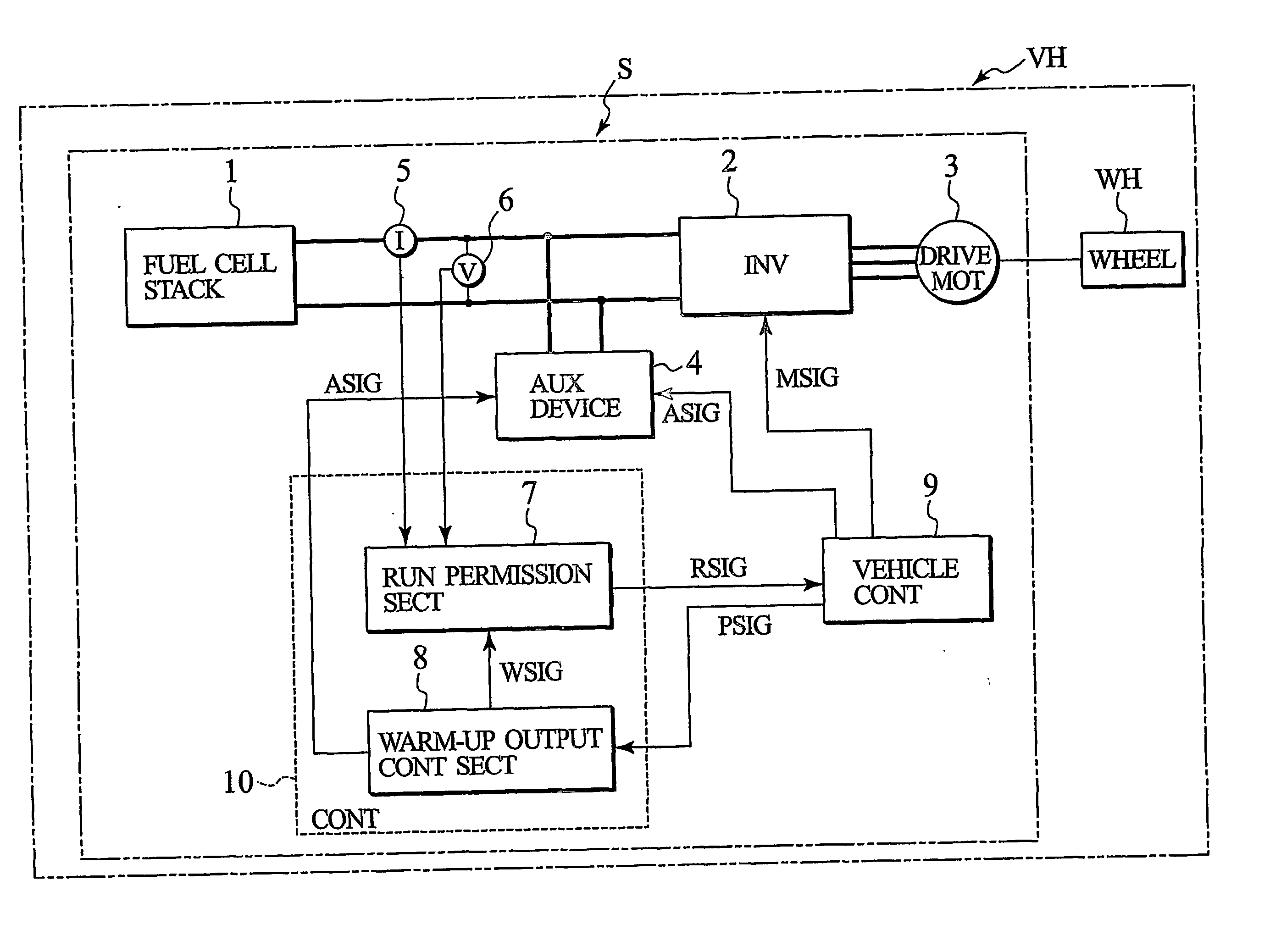
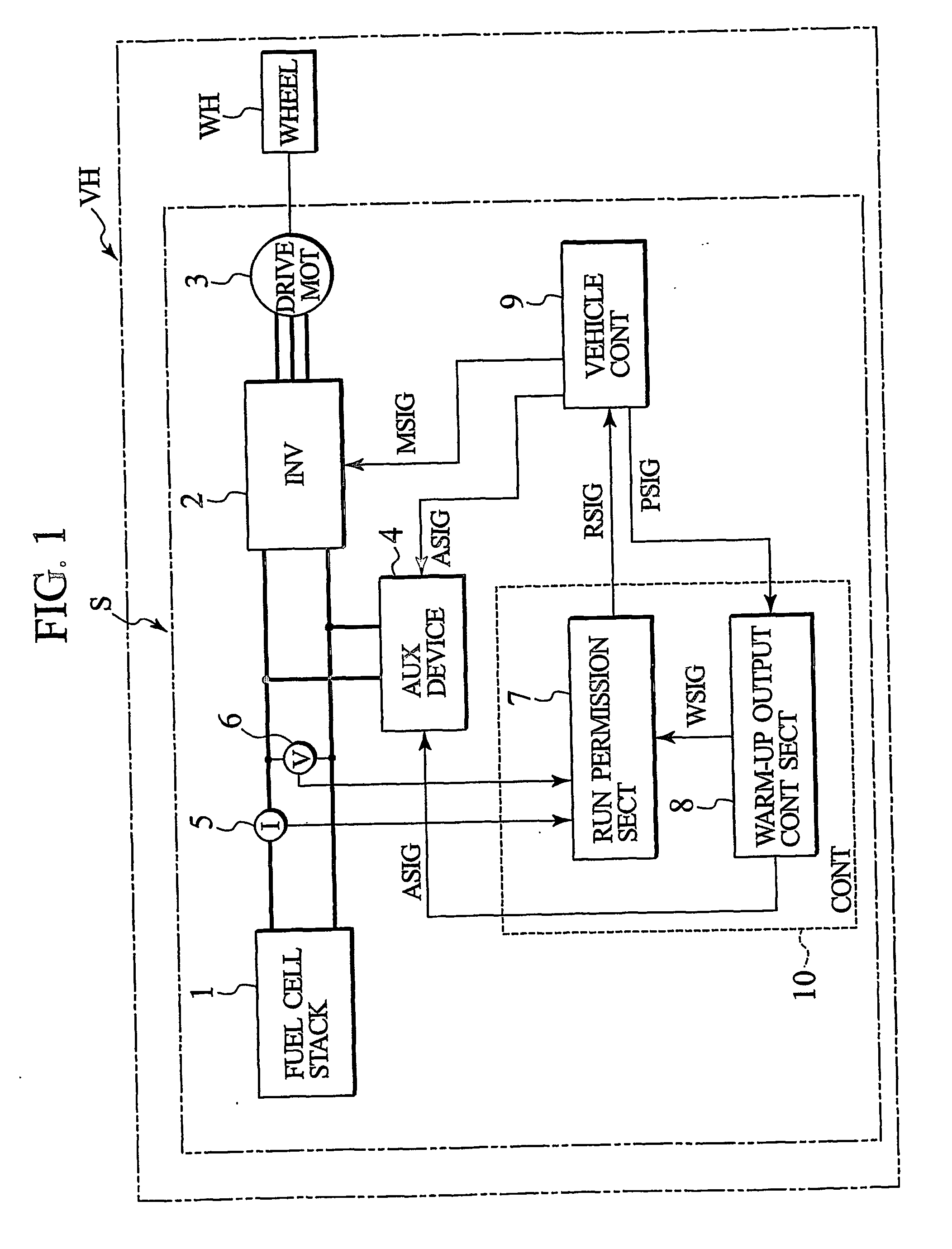
[0022]FIG. 1 is a block diagram showing a schematic structure of the vehicular fuel cell system of the presently filed embodiment.

[0023] In FIG. 1, the vehicular fuel cell system S is comprised of a fuel cell stack 1 that is supplied with fuel gas (hydrogen containing gas) and air (oxygen containing gas) to generate electric power, an inverter 2 converting DC power, delivered from the fuel cell stack 1, to AC power, a drive motor 3 supplied with AC power from the inverter 2 to drive wheels WH of a vehicle VH, an auxiliary device 4 that supplies the fuel cell stack 1 with air and coolant, an ammeter 5 that detects electric current of electric power generated by the fuel cell stack 1, a voltmeter 6 that detects voltage of electric power generated by the fuel cell stack 1, and a vehicle ...

second embodiment

[0074] Now, referring to FIGS. 8 to 10, detailed description is made of a control device of a vehicular fuel cell system and its related method of a second embodiment according to the present invention.

[0075]FIG. 8 is a flowchart showing the flow of start-up operation of a control device of a fuel cell system of the presently filed embodiment; FIG. 9 is a timing diagram illustrating variations in stack output, stack voltage and coolant temperature in terms of time during execution of start-up operation shown in FIG. 8; and FIG. 10 is a view illustrating the relationship between stack voltage and run available current of the presently filed embodiment. Also, start-up operation of the presently filed embodiment is executed in the same manner as that of the first embodiment shown in FIG. 1 except for operations in step S9 and step S10. Therefore, in the following description, description is mainly made of operations in step S9a and step S10a, associated with start-up operation of fuel...


PUM

PropertyMeasurementUnit
temperatureaaaaaaaaaa
electric poweraaaaaaaaaa
temperaturesaaaaaaaaaa

Abstract

A control device (10) for a vehicular fuel cell system (S) is provided with a warm-up output control section (8) operative, when a fuel cell system is started up under a low temperature condition and in case that a fuel cell stack of the fuel cell system is warmed up, causing the fuel cell stack to generate electric power to allow predetermined warm-up electric power to be taken out, and a run permission section (7) operative, during a period wherein the warm-up electric power is taken out by the warm-up output control section, to discriminate whether the fuel cell stack assumes a predetermined warm-up condition on the basis of one of a voltage value and an electric current value of the fuel cell stack. And, when discrimination is made that the fuel cell stack assumes the predetermined warm-up condition, the run permission section provides a vehicle with run permission.

Description

TECHNICAL FIELD [0001] The present invention relates to a control device of vehicular fuel cell system and a related method and, more particularly, to a control device of a vehicular fuel cell system that permits a fuel cell stack to generate electric power at a less power than a rated electric power during start-up at a low temperature condition, for thereby warming up the fuel cell system, and a related method. BACKGROUND ART [0002] Japanese Patent Application Laid-Open Publication No. 2002-305013 discloses a vehicular fuel cell system which during start-up of a vehicle at a low temperature condition such as a below-freezing temperature, permits a fuel cell stack to generate electric power at a predetermined power to achieve warm-up of a fuel cell prior to commencement to travel the vehicle, and which discriminates to find whether the warm-up of the fuel cell stack has been completed, referring to an air electrode (cathode) exhaust gas temperature, a temperature difference between...

Claims


Application Information

Patent Timeline
Patent Type & Authority Applications(United States)
IPC IPC(8): H01M8/04G05D11/00B60L11/18H01M8/00H01M16/00
CPCB60L11/1885Y02E60/50B60L11/1894H01M8/04007H01M8/04022H01M8/04141H01M8/04268H01M8/04358H01M8/04559H01M8/04589H01M8/04738H01M16/006H01M2250/20Y02T90/32Y02T90/34B60L11/1892B60L58/31B60L58/33B60L58/34Y02T90/40Y02E60/10
Inventor SAKAI, HIROMASA
Owner NISSAN MOTOR CO LTD
Why Eureka
Try Eureka