
Method for setting the retransmission timeout period in a packet switched communication network

a packet switched communication and timeout period technology, applied in the field of setting the retransmission timeout period in the packet switched communication network, can solve the problems of unnecessary retransmission of a given data unit, unnecessary delays in transmission, and unnecessary retransmission

Active Publication Date: 2006-10-19
TELEFON AB LM ERICSSON (PUBL)
View PDF5 Cites 13 Cited by
  • Summary
  • Abstract
  • Description
  • Claims
  • Application Information

AI Technical Summary

Benefits of technology

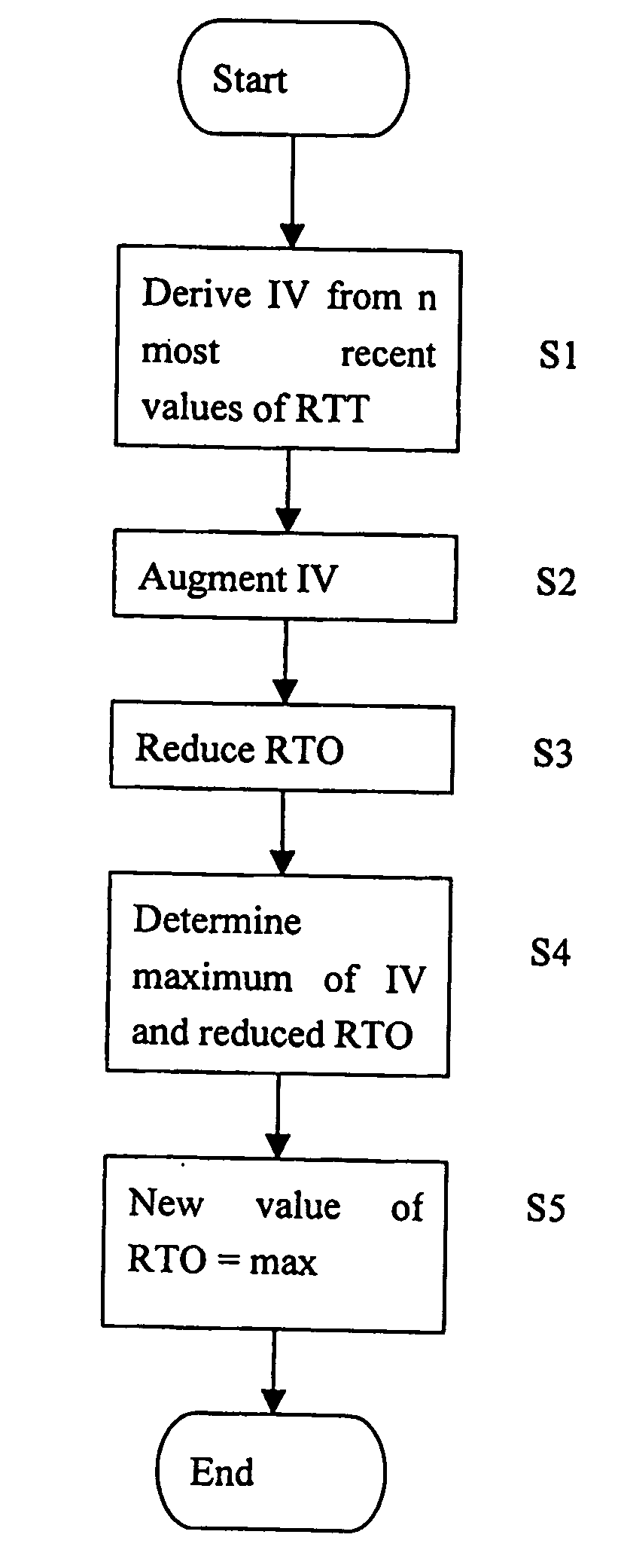
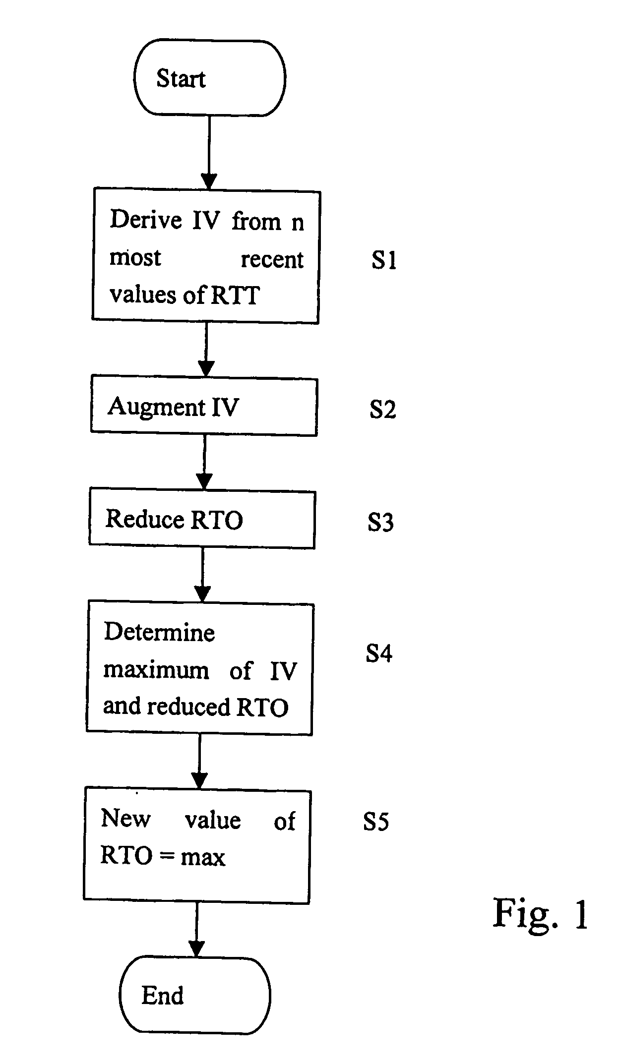
The present invention provides a method for updating the time-out period by using a procedure that takes into account the most recent values of the response time. This procedure includes a step of setting a new value of the time-out period by deriving an intermediate value from the n most recent values of the response time. The intermediate value is then augmented according to a predetermined augmenting procedure, and the current value of the time-out period is reduced according to a time-out period reducing procedure. The maximum from among at least the augmented intermediate value and the reduced current value of the time-out period is set as a new value of the time-out period. This method ensures good performance in experiments and solves the problems of the procedure proposed in RfC 2988.

Problems solved by technology

Namely, if the time-out period is too short, then the data unit sender will not wait long enough for the receipt of a feedback message, and thereby unnecessarily retransmit a given data unit.
Such an unnecessary retransmission is also called a spurious retransmission.
On the other hand, if the time-out period is set too long, then this leads to unnecessary delays in the transmission, as the retransmission of lost data units does not occur soon enough.
However, this is not always the case with the above-described method of updating RTO.
Therefore, although RTT has decreased, RTO has increased, which leads to unnecessary delay in the sending of data units.
Another problem with the above-described concept of RfC 2988 lies in the so-called magic numbers”⅛ and ¼ used as weighting factors.
However, these factors do not lead to satisfactory results in the updating of RTO when RTT measurements are made for every sent data unit, e.g. by using time stamps, when the number of outstanding data units is large, or if there is no significant variation between consecutive RTT samples.
This is undesirable, because RTT can be seen as the absolute minimum value for RTO, as one cannot expect to receive a feedback message in a time shorter than RTT.
As a consequence, the above-described phenomenon of RTO “collapsing” into RTT leads to a highly increased probability of spurious retransmissions.

Method used


Image

  • Method for setting the retransmission timeout period in a packet switched communication network
  • Method for setting the retransmission timeout period in a packet switched communication network
  • Method for setting the retransmission timeout period in a packet switched communication network

Examples


Embodiment Construction

[0026] In the following description of examples, reference will be made to terms and expressions known from the Transmission Control Protocol (TCP), such as Retransmission Time-Out period or RTO and Round Trip Time or RTT for the response time indicative of the time that passes between the sending of a data unit and the receiving of a feedback message relating to said data unit. These terms and abbreviations are used for convenience and simplicity, as they are well understood by people skilled in the art, but it is not intended to restrict the application of the concept of the present invention to TCP or any other particular communication protocol. As such, the above-mentioned expressions and abbreviations are used generically. Namely, the concept of the present invention for updating a time-out period can be used in any protocol that provides a retransmission time-out feature, such as e.g. SCTP (Stream Control Transmission Protocol).

[0027]FIG. 1 shows a flow chart of a basic embod...


PUM


Abstract

The present invention relates to a method for updating the value of a time-out period in a data unit sender. The updating comprises deriving an intermediate value from the n most recently measured values of a response time, augmenting the intermediate value, reducing the current value of the time-out period, determining the maximum from among at least the augmented intermediate value and the reduced current value of the time-out period, and setting a new value of the time-out period to set a maximum value.

Description

FIELD OF THE INVENTION [0001] The present invention relates to a method for updating the value of a time-out period in a data unit sender, and to a data unit sender arranged to perform the method. BACKGROUND OF THE INVENTION [0002] Generally, in the field of communication one distinguishes between circuit-switched connections and data unit switched communications. In a data unit switched connection, an amount of data to be sent is divided into data units, and these data units are sent in accordance with a protocol governing the communication. It may be noted that the data units receive different names in the context of different protocols, such as packets, frames, segments, etc., In the present application the term “data unit” is used generically to relate to any such subdivision of data. [0003] In order to ensure the reliable transmission of data, many protocols provide the feature of data unit retransmission. More specifically, data unit retransmission means that a data unit recei...

Claims


Application Information

Patent Timeline
Patent Type & Authority Applications(United States)
IPC IPC(8): H04B7/00H04Q7/20H04L1/18H04L12/56H04L29/06
CPCH04L1/188H04L47/10H04L69/163H04L47/283H04L69/16H04L47/193
Inventor LUDWIG, REINEREKSTROM, HANNES
Owner TELEFON AB LM ERICSSON (PUBL)
Learn More