
Artificial prosthesis

a technology of artificial prosthesis and prosthesis, applied in the field of artificial prosthesis, can solve the problems of end plates, dislocation of end plates, and most interosseal prosthetic devices suffer, and achieve the effect of increasing the potential for fractures

Inactive Publication Date: 2006-10-19
SHELOKOV ALEXIS PAUL
View PDF28 Cites 18 Cited by
  • Summary
  • Abstract
  • Description
  • Claims
  • Application Information

AI Technical Summary

Benefits of technology

[0009] The present invention finds widespread use in all interosseal implant locations by providing a viable mechanical substitute with enhance function, decreased pain and the durability necessary for long-term use. For example, when used in conjunction with bone morphogenic protein, the present invention leads to a reduction in recovery time, improved natural segmental motion, pain relief and durability for long-term use.
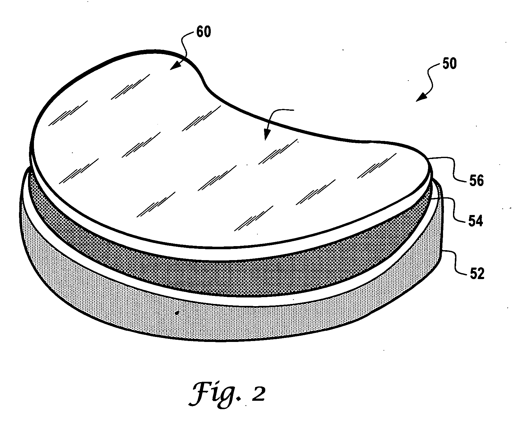
[0013] When used in any joint, apex of the convex portion of the third disc may be selected to control or improve lateral flexion, rotation or flexion / extension depending on the site of implantation. Furthermore, the discs may also include an inferior surface comprising a periphery that complements and attaches to the load-bearing rim of a bone upon implantation. Depending on the site of implantation, the prosthesis may be an artificial shoulder joint, an artificial hip joint, an artificial knee joint, an artificial elbow joint, an artificial ankle joint, an artificial wrist joint, an artificial carpo-metacarpal joint, an artificial metacarpo-phalangeal joint, an artificial interphalangeal joint and an artificial metatarso-phalangeal joint, to list a few. To provide additional mechanical strength to the prosthesis upon implantation, the first, the third or both discs may include one or more holes therethrough for use in securing the first, the third or both discs to a bone. The first, the second, the third outer disk periphery, and combinations thereof, may be chamfered, kidney shaped and / or coated.

Problems solved by technology

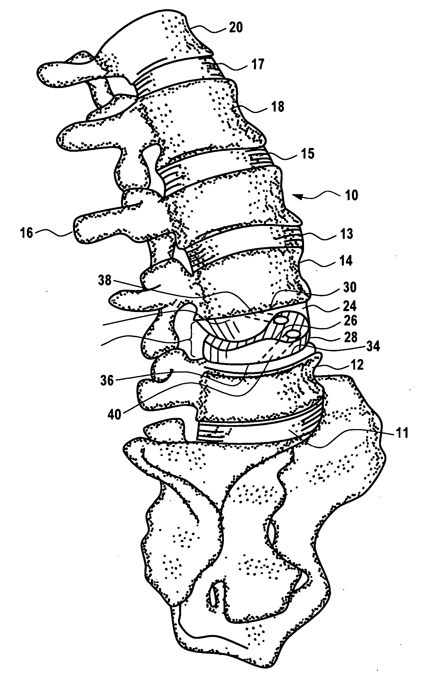
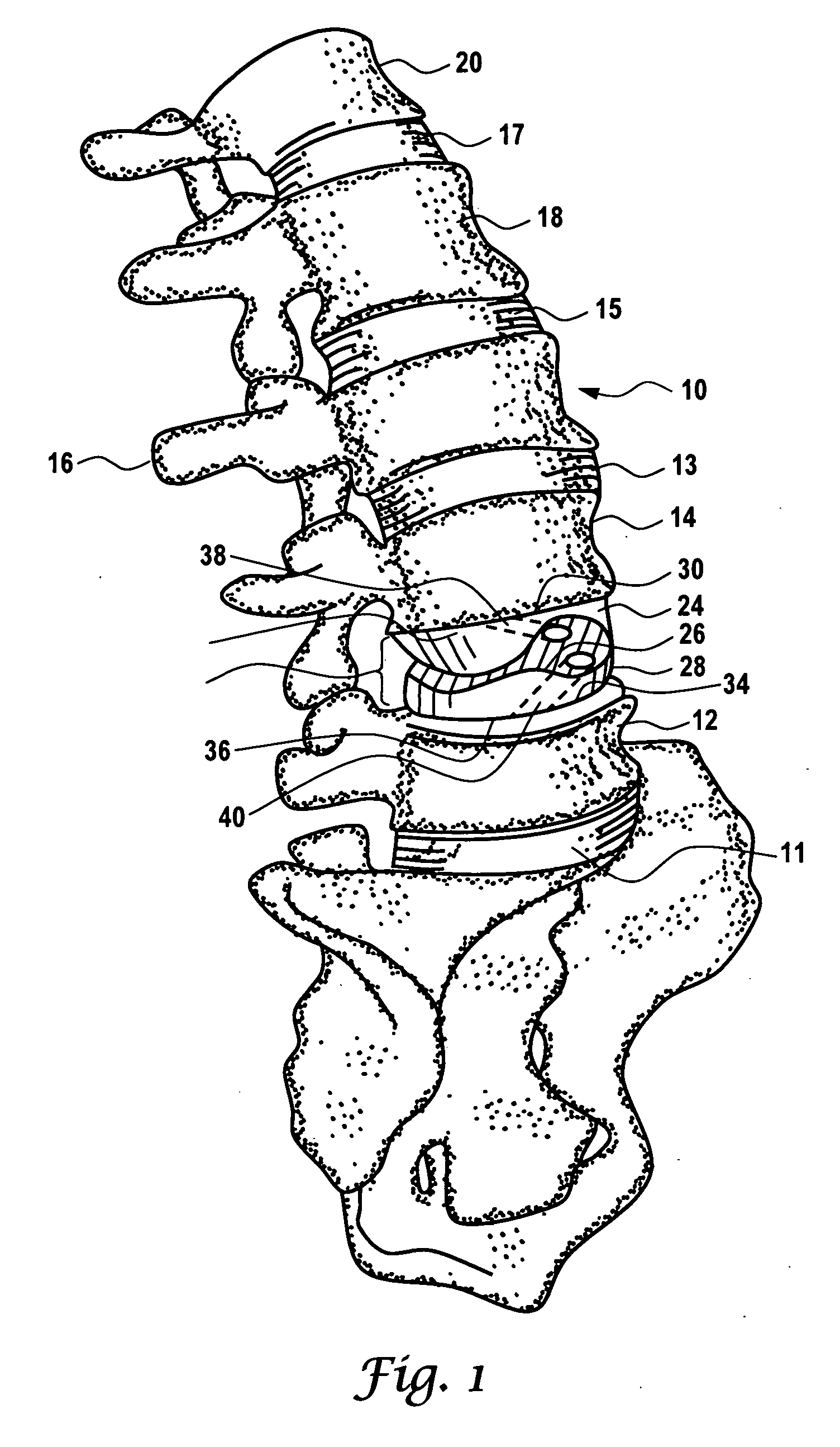
The present inventor has recognized that most interosseal prosthetic devices suffer from disadvantages such as the movement of the end plates, dislocation of the endplates, cold flow, ossification of the annulus, and particulate wear and debris of the component parts.
Similar problems have been found with interosseal implants for use with a wide variety of joints, e.g., degenerative hips and knees.

Method used


Image

  • Artificial prosthesis
  • Artificial prosthesis
  • Artificial prosthesis

Examples


Embodiment Construction

[0024] While the making and using of various embodiments of the present invention are discussed in detail below, it should be appreciated that the present invention provides many applicable inventive concepts that can be embodied in a wide variety of specific contexts. The specific embodiments discussed herein are merely illustrative of specific ways to make and use the invention and do not delimit the scope of the invention.

[0025] To facilitate the understanding of this invention, a number of terms are defined below. Terms defined herein have meanings as commonly understood by a person of ordinary skill in the areas relevant to the present invention. Terms such as “a”, “an” and “the” are not intended to refer to only a singular entity, but include the general class of which a specific example may be used for illustration. The terminology herein is used to describe specific embodiments of the invention, but their usage does not delimit the invention, except as outlined in the claim...


PUM


Abstract

The present invention is directed to an artificial prosthesis (50) that includes a first disc (56) with a first disc periphery (60), a first disc superior surface (58) and a first disc inferior surface (68) having a first mating portion (90), a second disc (54) having a second mating portion (80) that is substantially complementary to the first disc mating portion (90) and a convex surface (65), and a third disc (52) having a concave superior surface (62) that substantially complements the convex surface of the second disc (65).

Description

CROSS-REFERENCE TO RELATED APPLICATIONS [0001] This application claims priority to U.S. Provisional Application Ser. No. 60 / 672,318, filed Apr. 18, 2005, the contents of which are incorporated by reference herein in its entirety.TECHNICAL FIELD OF THE INVENTION [0002] The present invention relates in general to the field of artificial prosthesis, and more particularly, to an improved artificial prosthesis for use in various joints with reduced material fatigue and improved patient comfort. BACKGROUND OF THE INVENTION [0003] Without limiting the scope of the invention, its background is described in connection with spinal joint prosthesis. [0004] A wide variety of artificial prosthesis are used to replace chronically injured or ruptured intervertebral discs; primarily, in the lower lumbar region of the spine. These prostheses generally employ one, two, three or more individual elements having a wide range of constructs including ball and socket joints, gel filled enclosures, spring-b...

Claims


Application Information

Patent Timeline
IPC IPC(8): A61F2/44A61F2/30
CPCA61F2/4425A61F2310/00239A61F2002/30331A61F2002/30365A61F2002/30677A61F2002/3068A61F2002/30937A61F2002/443A61F2220/0033A61F2230/0015A61F2250/0068A61F2310/00017A61F2310/00023A61F2310/00029A61F2310/00059A61F2002/30133
Inventor SHELOKOV, ALEXIS PAUL
Owner SHELOKOV ALEXIS PAUL
Learn More