Biofuel conversion process

a biofuel and conversion process technology, applied in the field of biofuel conversion process, can solve problems such as inefficiency of processes, and achieve the effect of enhancing energy conten

Inactive Publication Date: 2006-10-26
NAKAMURA NORIKAZU
View PDF6 Cites 24 Cited by
  • Summary
  • Abstract
  • Description
  • Claims
  • Application Information

AI Technical Summary

Benefits of technology

[0010] The present invention is directed to a process, method, apparatus and materials for efficient conversion of waste vegetable oils into biofuel that does not use methanol as a reactant or catalyst. The resulting biofuel is mixed with kerosene or heavy oil to form a stable diesel fuel grade fuel that is mixable with diesel fuel. In addition, the process and apparatus are also applicable to the conversion of virgin vegetable oils and other waste or virgin oils, such as used motor oil, into fuels or fuel additives. In the process, the waste oils are mixed with a blend of catalyst and absorption powders in a tank and heated to about 80 degrees centigrade for 40 to 60 minutes. The composition is then passed through a filter to remove the added powders, any sediments and certain contaminates in the oil including most carbon solids, as well as certain fatty acids and constituents of the waste oil. The mixing and filtering process clarifies the resulting biofuel and enhances the energy content from 4,000 to 5,000 calories / gram to 9,000 to 10,000 calories / gram.
[0011] The clarified biofuel resulting from vegetable oils may then be blended with kerosene and filtered through the filter bed containing the removed sediments from the first filtering process or a powder mixture of absorption powders is added to the blended biofuel and kerosene, mixed for 40 to 60 minutes and then filtered. A similar process can be used to recover and generate fuel grade oil from used or waste motor oil, with a resulting product that can be mixed with the biofuel derived from vegetable oils as a replacement for the kerosene additive to produce a light grade or heavy grade fuel oil.

Problems solved by technology

This process is inefficient as it requires extensive storage periods and there is still a significant amount of sediment contaminated waste oil that is sent for disposal.
However, the methanol based processes result in a biofuel that does not mix well with other fuels, such as diesel fuel, so a small quantity of methanol derived biofuels must be mixed with other fuels, such as diesel fuel for automobiles.

Method used


Image

  • Biofuel conversion process
  • Biofuel conversion process
  • Biofuel conversion process

Examples


Embodiment Construction

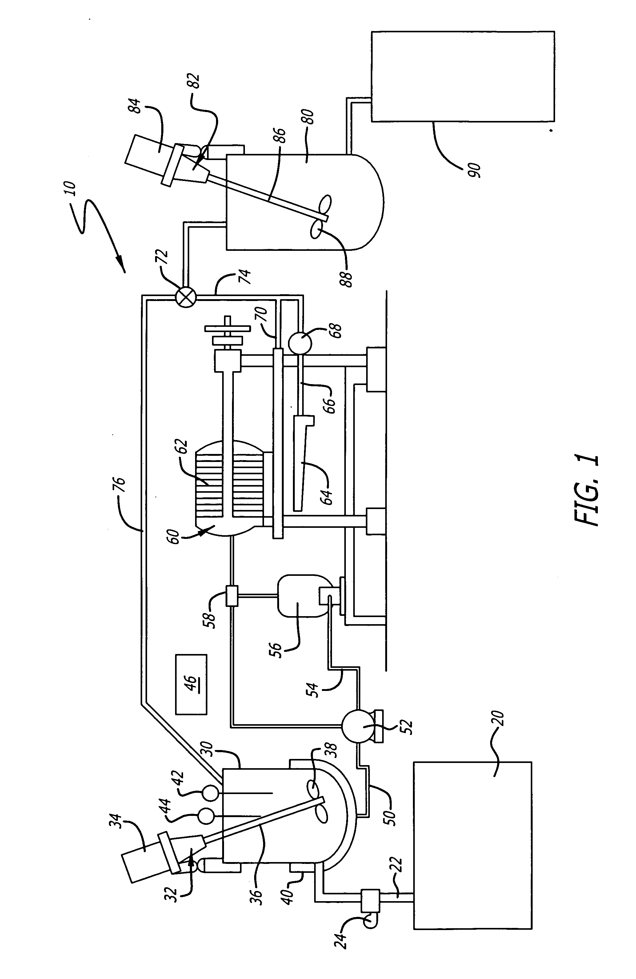
[0015]FIG. 1 schematically depicts a basic biofuel conversion apparatus 10 according to a first aspect of the present invention. The apparatus 10 includes an oil tank 20 that is either a large storage tank or plurality of storage drums. Oil from tank 20 is routed via pipe 22 and pump 24 to a catalyst tank 30. The catalyst tank 30 includes a mixing apparatus 32, for example a motor 34, shaft 36 and impeller 38. The lower section of the catalyst tank 30 includes a heating assembly 40, for example a steam heat exchange system. The catalyst tank 30 also includes a temperature sensor 42 and may include a level sensor 44. The temperature sensor 42 is connected to a controller 46 that controls the pump 24 and the timing of the process as well as the temperature control for the heating assembly 40.

[0016] Upon completion of a reaction period in the catalyst tank 30, the mixture is delivered via a pipe 50 to pump 52. The output of pump 52 is directed to a pipe 54. Pipe 54 delivers the mixtur...


PUM

PropertyMeasurementUnit
temperatureaaaaaaaaaa
weight percentaaaaaaaaaa

Abstract

A process, method, apparatus and materials for efficient conversion of waste vegetable oils into biofuel that does not use methanol as a reactant or catalyst. The resulting biofuel is mixed with kerosene or heavy oil to form a stable diesel fuel grade fuel that is mixable with diesel fuel. In addition, the process and apparatus are also applicable to the conversion of virgin vegetable oils and other waste or virgin oils, such as used motor oil, into fuels or fuel additives.

Description

BACKGROUND OF THE INVENTION [0001] Biofuel is a type of fuel made using non-petroleum based oils converted to allow combustion within power plants and engines as a replacement for heavy oils and diesel fuel. Biofuels have desirable burning characteristics and are derived from renewable resources. For example, biofuels may be derived from vegetable oils processed from crops. [0002] Vegetable oils are used extensively in food preparation in restaurants, hotels, hospitals and other large institutions. The use of vegetable oils in food preparation generates substantial waste product that must be appropriately disposed of. Processing of these waste vegetable oils into biofuel thus serves two beneficial purposes, creation of a clean and environmentally friendly fuel source and the elimination of waste disposal requirements. [0003] To understand the scope of the potential use of the present invention it is beneficial to appreciate the extent of the generation of waste vegetable oils in our...

Claims


Application Information

Patent Timeline
Patent Type & Authority Applications(United States)
IPC IPC(8): C10L1/00
CPCC10G1/08Y02E50/13C10L1/026C10G1/086Y02E50/10Y02P30/20
Inventor NAKAMURA, NORIKAZU
Owner NAKAMURA NORIKAZU
Why Eureka
Try Eureka