Passive wafer support for particle free wafer acceleration

a technology of acceleration and wafers, applied in the direction of transportation and packaging, cranes, coatings, etc., can solve the problems of particle generation, larger contact area, and complicated system

Inactive Publication Date: 2006-10-26
SOKUDO CO LTD
View PDF15 Cites 6 Cited by
  • Summary
  • Abstract
  • Description
  • Claims
  • Application Information

AI Technical Summary

Benefits of technology

[0022] Yet another embodiment of the present invention provides a method for handling a substrate. The method comprises providing a support plate having at least one pad formed an upper surface and a substantially uniform thermal resistance across the upper surface, positioning the substrate on the at least one pad, and transferring the substrate by moving the support plate.

Problems solved by technology

However, since the substrate is only supported by a few pins, the substrate is likely to deform because of gravity and the support pressure is increased which may lead back to particle generation.
Additionally, decreased friction introduces a problem of slippage, where a substrate will slide over a substrate support during transferring losing the precise positioning crucial to the semiconductor process.
Consequently, the system becomes more complicated and contact area becomes larger and more particle contaminations are introduced.
Thermal stress also becomes a problem especially handling a substrate after a process performed in an elevated temperature.
In the one hand, the substrate is not cooled down uniformly because the thermal resistance of the contact area is generally different from where there is no contact.
In the other hand, the substrate may shrink in size while cooling down, thus introducing friction, slippage, and deformation, especially for substrates of large size.
For a shuttle plate constructed like the shuttle plate 80, a baked substrate may not cool down evenly between the areas contacting the proximity pins and the areas exposed directly to the environment, thus causing thermal or even mechanical stress.
In conclusion, a shuttle plate of prior art are susceptible to thermal stress, particle contamination and slippage.

Method used


Image

  • Passive wafer support for particle free wafer acceleration
  • Passive wafer support for particle free wafer acceleration
  • Passive wafer support for particle free wafer acceleration

Examples


Embodiment Construction

[0035] Embodiments of the invention generally provide a substrate support plate having thin pads of elastomer which has high static friction coefficient and affords lack of residue. The thin pads are configured to keep a substrate from touching the substrate support plate. The thickness of the thin pads are designed such that the thermal resistance of the thin pads are substantially equal to the thermal resistance of the air gap between the substrate support plate and the substrate supported by the thin pads. Thus, the substrate support plate of the present invention provides high friction between the substrate and the supporting surface, low particle generation, and substantially uniform heat transfer property.

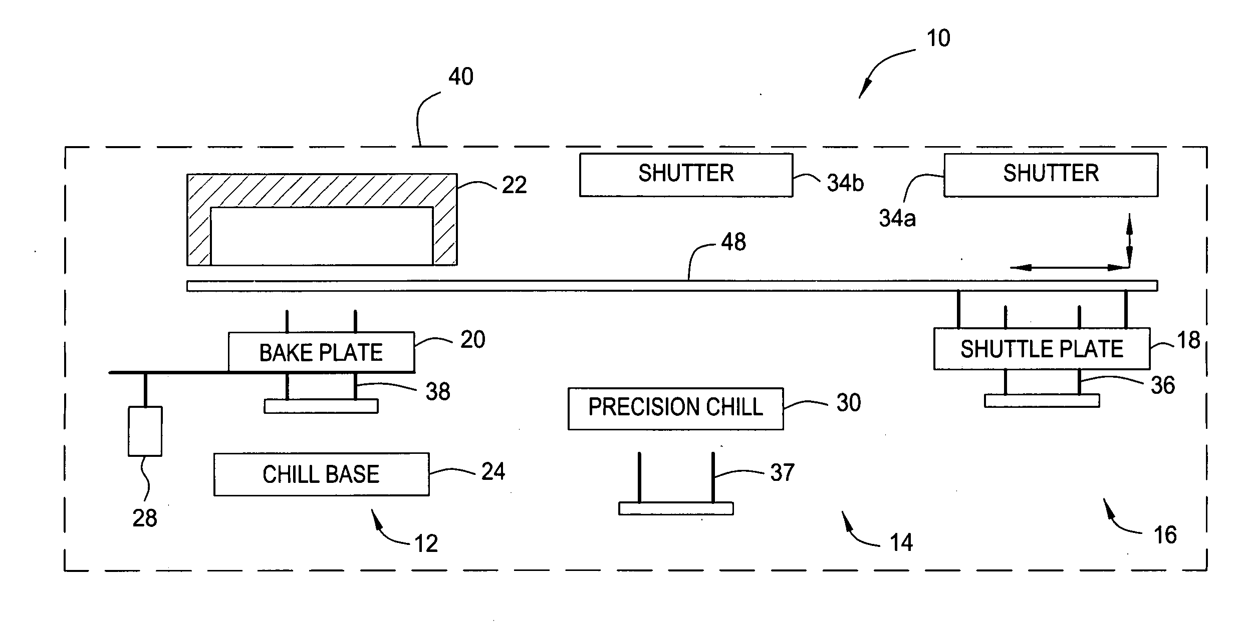
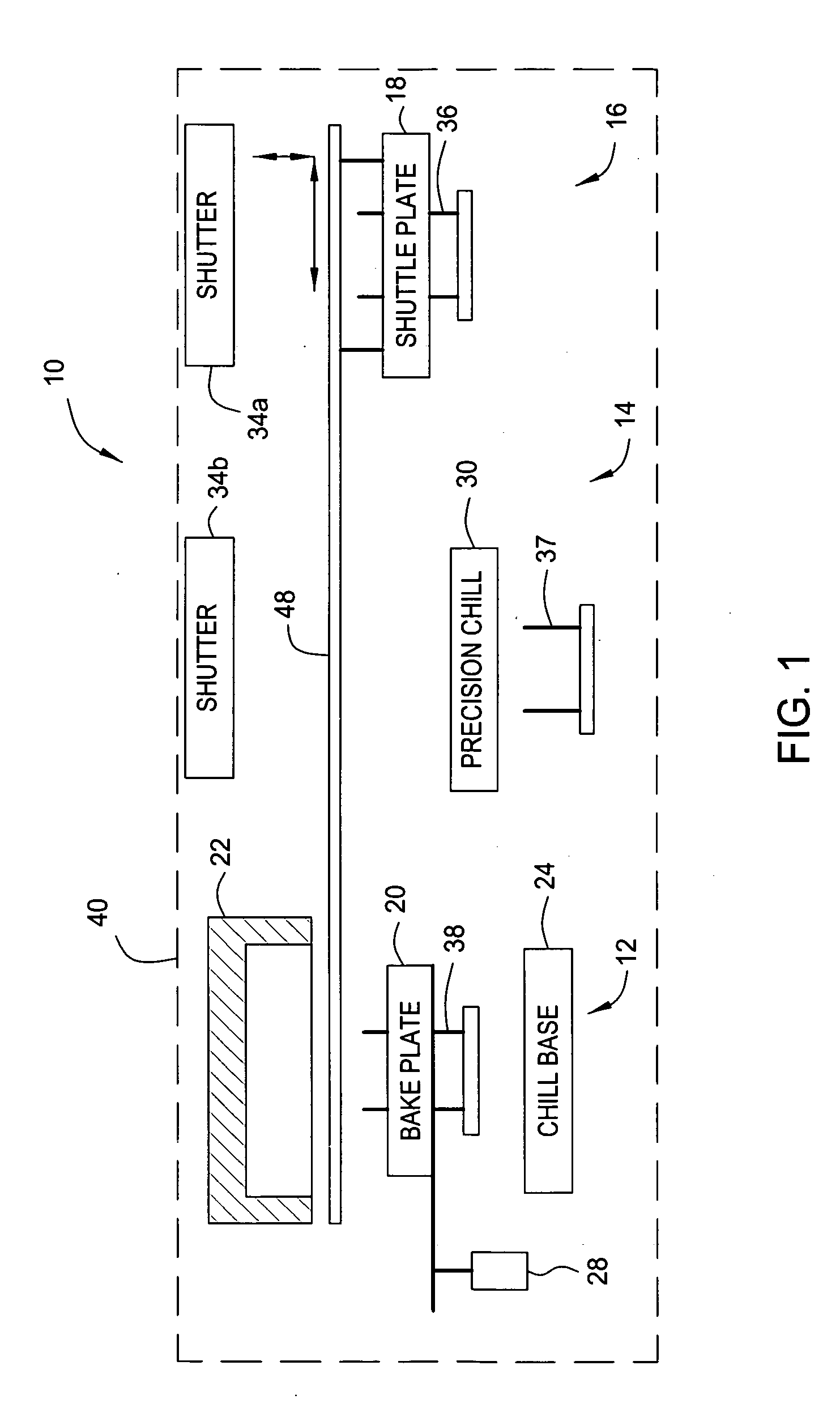
[0036]FIG. 3 is a schematic view of one embodiment of a shuttle plate 100 of the present invention. The shuttle plate 100 is configured to support and transfer a substrate in a semiconductor processing system, such as the integrated thermal unit 10 shown in FIG. 1.

[0037] Th...


PUM

PropertyMeasurementUnit
distanceaaaaaaaaaa
dynamic friction coefficientaaaaaaaaaa
diameteraaaaaaaaaa

Abstract

The present invention provides an apparatus and a method of handling and transferring substrate in reduced particle contamination and thermal stress, as well as increased speed. One embodiment of the present invention provides an apparatus for handling a substrate. The apparatus comprises a support plate, and at least one pad protruding an upper surface of the support plate. The pad is configured to support a backside of the substrate so that the backside of the substrate is a first distance away from the upper surface of the support plate. The thermal resistance of the pad is substantially equal to the thermal resistance of the medium between the substrate and the upper surface.

Description

CROSS-REFERENCE TO RELATED APPLICATIONS [0001] This application is continuation in part of U.S. patent application Ser. No. 11 / 111,155, filed on Apr. 20, 2005, entitled “Purged Vacuum Chuck with Proximity Pins”, which is herein incorporated by reference.BACKGROUND OF THE INVENTION [0002] 1. Field of the Invention [0003] Embodiments of the present invention generally relate to apparatus and method for handling semiconductor substrates. [0004] 2. Description of the Related Art [0005] In modern semiconductor processing, multilayered features are fabricated on semiconductor substrates in a cleanroom environment using specific processing recipes having many processing steps. A semiconductor process system may include single process chambers and cluster tools which integrate a number of process chambers to perform a sequential processing steps without removing substrates from a highly controlled processing environment. The process chambers may include, for example, substrate preconditioni...

Claims


Application Information

Patent Timeline
Patent Type & Authority Applications(United States)
IPC IPC(8): B65G25/00C23C16/00H01L21/306
CPCH01L21/67103H01L21/6838H01L21/67748
Inventor HERCHEN, HARALD
Owner SOKUDO CO LTD
Why Eureka
Try Eureka