Spatially Combined Laser Assembly And Method Of Combining Laser Beams

Active Publication Date: 2013-12-12
COHERENT INC
View PDF5 Cites 0 Cited by
  • Summary
  • Abstract
  • Description
  • Claims
  • Application Information

AI Technical Summary

Benefits of technology

The present invention provides a diode laser assembly that produces a spatially combined laser beam with an adjustable pitch and uniform thermal resistance for each diode bar. The assembly has a generally flat base plate with multiple diode bars aligned with reflectors for re-direction of the laser beams. The position and far field pointing of the laser beams can be adjusted by rotating or translating the reflectors. This assembly offers advantages such as minimizing the stacking pitch, maximizing beam quality, and ensuring uniform thermal resistance for the diode bars. The flat base plate is lightweight, cost-effective, smoother, and more accurately dimensioned than machined base plates. The assembly can be easily cooled with water or any other liquid.

Problems solved by technology

Although diode laser emitters are very efficient at producing laser beams, the quality of the laser beam produced decreases when the power applied to the diode laser emitter is increased.
One problem with diode bars is that they produce heat which must be conveyed away from the diode laser emitters for them to continue operating properly.
Another problem with diode bars is that a single diode bar is still not powerful enough for some applications.
While this approach may be suitable for liquid cooled heat sinks, it is generally not suitable for convection cooled heat sinks due to a lack of surface area for dispensing heat to the air.
Additionally, the stacking pitch, or the distance between the laser beams of adjacent diode bars, is dictated by the width of the heat sinks and cannot be adjusted.
Large heat sinks will result in a spatially combined laser beam with a large stacking pitch, a large beam parameter product (BPP) and a low beam quality, whereas small heat sinks may improve upon these properties of the spatially combined laser beam but do not provide adequate cooling to the diode bars.
Therefore, due to inherent tolerances in the manufacturing of the stepped base plate and the inability of the step-and-minor assembly to adjust the vertical position of the laser beams, the steps in the base plate are generally spaced vertically by a larger distance than would otherwise be ideal.
Consequently, the resulting laser beam from the step-and-mirror assembly has an increased stacking pitch, increased BPP and a decreased beam quality.
For example, they typically are machined into the base plate, resulting in increased manufacturing costs and an increased surface roughness, which could reduce the thermal conductivity between the diode bars and the base plate.
Moreover, once machined, the steps cannot be adjusted to change the pitch of the combined laser beam.
Finally, if coolant is used to cool the base plate, a complex and difficult to form coolant channel may be required to convey the coolant through the steps to provide adequate cooling to the diode bars.

Method used


Image

  • Spatially Combined Laser Assembly And Method Of Combining Laser Beams
  • Spatially Combined Laser Assembly And Method Of Combining Laser Beams
  • Spatially Combined Laser Assembly And Method Of Combining Laser Beams

Examples


Embodiment Construction

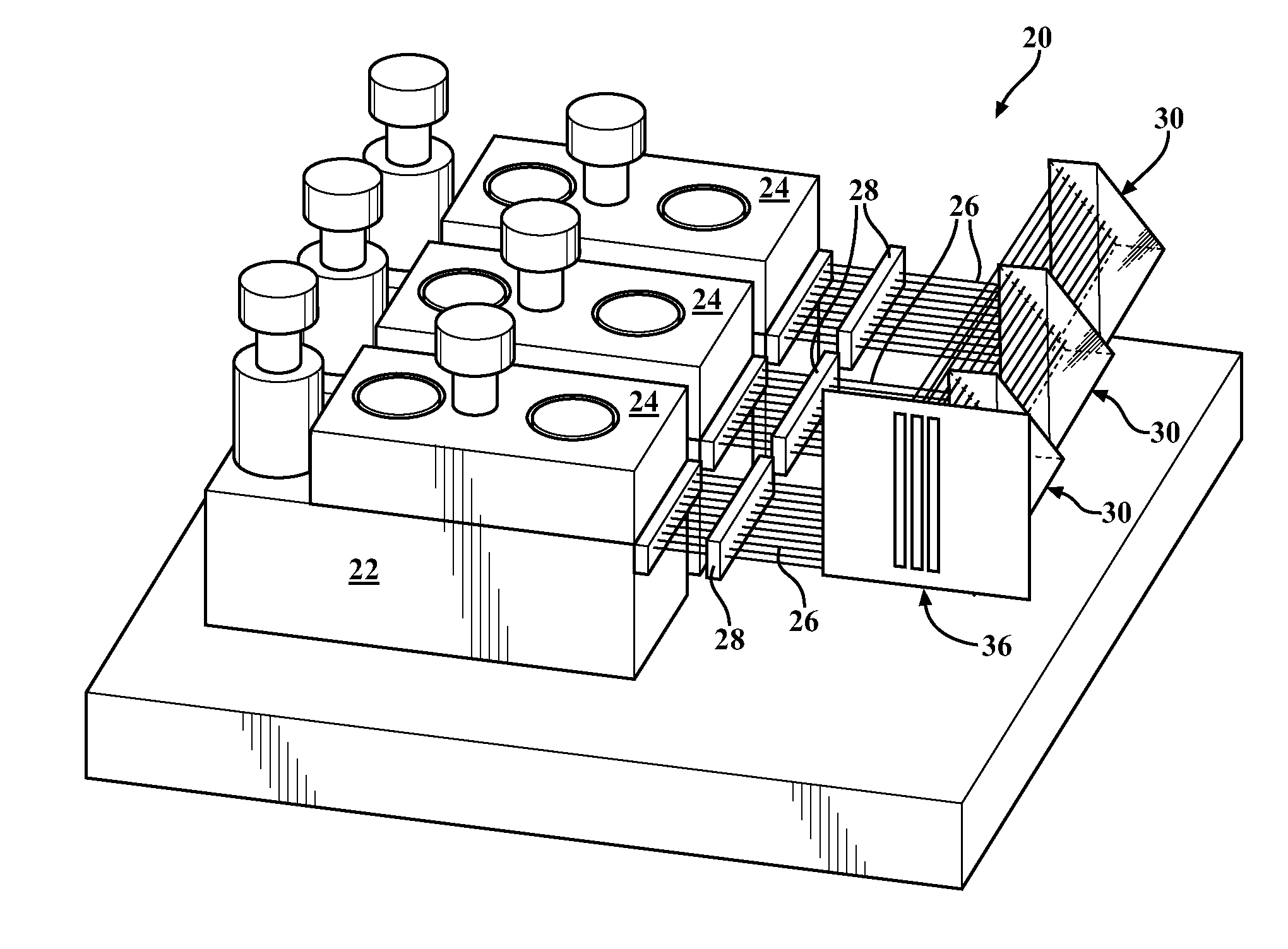
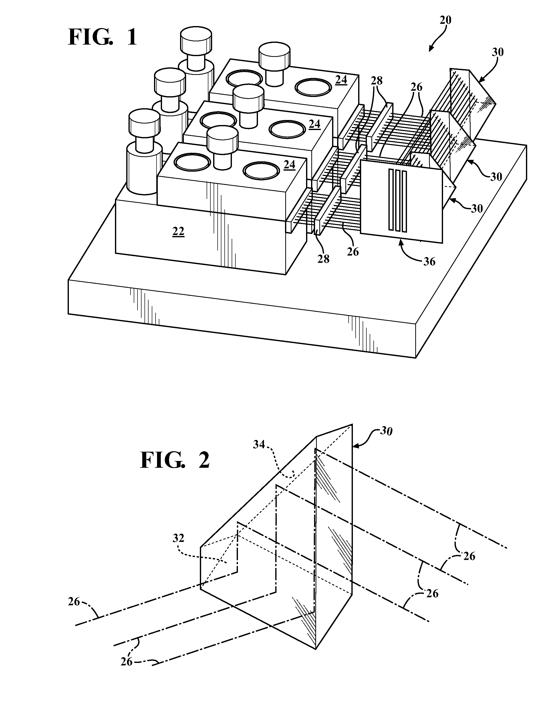
[0024]Referring to the Figures, wherein like numerals indicate corresponding parts throughout the several views, a diode laser assembly 20 constructed according to one aspect of the present invention is generally shown in FIG. 1. The diode laser assembly 20 includes a generally flat base plate 22 having a plurality of mounting surfaces for supporting a plurality of diode bars 24, each of which includes a plurality of diode laser emitters arranged in a one-dimensional array. Alternately, the diode laser emitters could be mounted on the base plate 22 without the diode bars 24, if desired. As shown, all of the diode bars 24 are disposed in the same vertical plane, and each is oriented to emit a laser beam 26 in a first, or lateral, direction.

[0025]In addition to supporting the diode bars 24, the flat base plate 22 functions as a heat sink, which can be liquid or convectively cooled, to convey heat away from the diode bars 24. The base plate 22 is of one piece of material and has a gene...


PUM


Abstract

A diode laser assembly including a plurality of diode bars disposed on a generally flat base plate and being oriented to emit a plurality of laser beams in a first direction. A reflector is spaced in the first direction from each of the diode bars in the first. Each reflector has at least two reflecting surfaces, one for reflecting the laser beams into a second direction different from the first direction and the other for reflecting the laser beams into a third direction different from the first and second directions to produce a spatially combined laser beam. Each reflector is moveable relative to one another and to the diode bars for adjusting the individual laser beams within the spatially-combined laser beam for optimizing the quality of the spatially combined laser beam.

Description

CROSS-REFERENCE TO PRIOR APPLICATION[0001]This PCT patent application claims the benefit of U.S. Provisional Patent Application Ser. No. 61 / 434,574 filed Jan. 20, 2011, entitled “Spatially Combined Diode Laser Assembly,” the entire disclosure of the application being considered part of the disclosure of this application and hereby incorporated by reference.BACKGROUND OF THE INVENTION[0002]1. Field of the Invention[0003]The present invention relates to lasers. More specifically, the present invention relates to an assembly for combining the beams of a plurality of diode lasers into a spatially combined laser beam.[0004]2. Brief Description of the Prior Art[0005]Diode lasers, otherwise known as semiconductor lasers, are well known laser light sources for producing laser beams with a high brightness and a high beam quality. Because of these properties, diode lasers are used in many everyday applications including, for example, CD players, DVD players, laser printers, and bar-code reade...

Claims


Application Information

Patent Timeline
IPC IPC(8): G02B19/00
CPCG02B19/0019G02B19/0057
Inventor KOENNING, TOBIAS
Owner COHERENT INC
Why Eureka
Try Eureka