
Jet generating device and electronic apparatus

Inactive Publication Date: 2006-10-26
SONY CORP
View PDF6 Cites 20 Cited by
  • Summary
  • Abstract
  • Description
  • Claims
  • Application Information

AI Technical Summary

Benefits of technology

[0008] In recent years, the amount of heat that is generated by increased IC clocking is increasing. Therefore, for example, in order to destroy a temperature boundary layer formed near a radiating fin due to the generation of the heat thereof, a larger amount of air is typically sent towards the IC or the radiating fin than it has been up until now. In a method for discharging air with a vibrating plate which reciprocates periodically, such as those described in the aforementioned four documents, the amount of air that is discharged can be increased by increasing the vibration amplitude of the vibrating plate. However, the larger the vibration amplitude of the vibrating plate, the larger the noise. Therefore, for practical purposes, the vibrating plate is typically operated with a small vibration amplitude at which the noise level does not bother anyone.

Problems solved by technology

However, the larger the vibration amplitude of the vibrating plate, the larger the noise.
One cause of this noise is sound waves that are generated by a periodic variation in air pressure in a chamber caused by a reciprocating movement of a vibrating plate.
Therefore, the higher the vibration amplitude, the more serious is the problem of noise produced by these sound waves.
Another cause of the noise is airflow sound caused by a disturbance in airflow resulting from a reciprocating movement of the vibrating plate.
Therefore, in the chamber, a disturbance occurs in the airflow due to a structural member (such as a driving unit or the suction-exhaust opening) which inhibits the smooth flow of the air, or a disturbance occurs in the flow of air passing through the suction-exhaust opening at a high speed or in the airflow outside the suction-exhaust opening.
Consequently, noise resulting from the airflow sound produced by such disturbances becomes a problem.

Method used


Image

  • Jet generating device and electronic apparatus
  • Jet generating device and electronic apparatus
  • Jet generating device and electronic apparatus

Examples


Embodiment Construction

[0039] Embodiments of the present invention will hereunder be described with reference to the drawings.

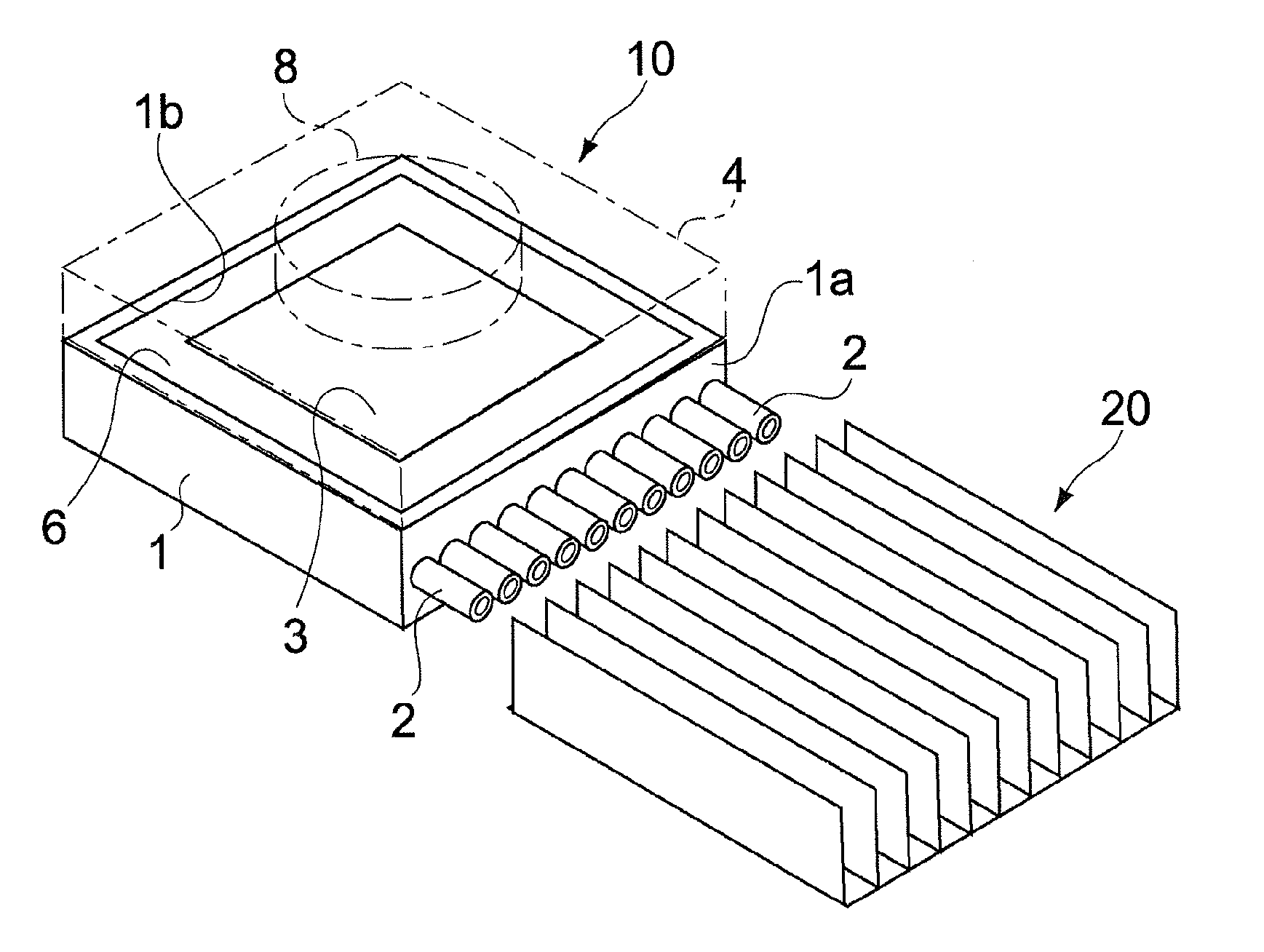
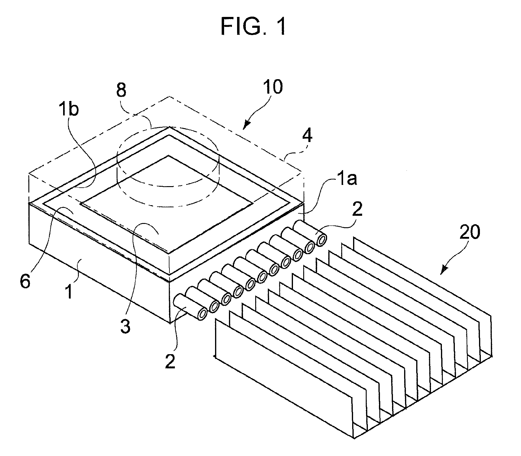
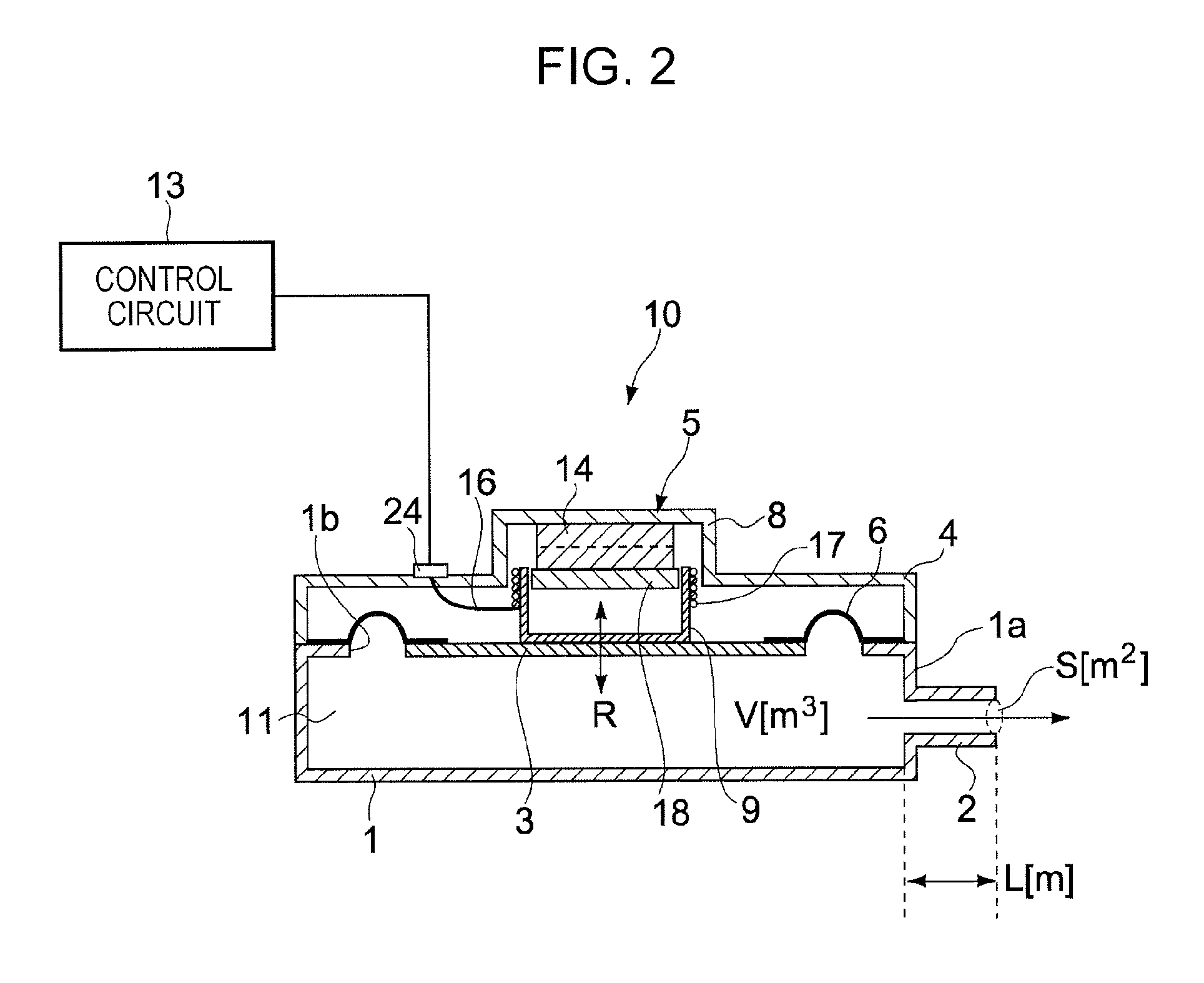
[0040]FIG. 1 is a perspective view of a jet generating device and a heat sink according to an embodiment of the present invention. FIG. 2 is a sectional view of a jet generating device 10 shown in FIG. 1.

[0041] The jet generating device 10 includes a housing 1 having a rectangular hole 1b in an upper portion of the housing 1. A rectangular resilient supporting member 6 is mounted to a periphery of the hole 1b of the housing 1, and supports a vibrating plate 3 serving as a vibrating member. A chamber 11 is formed by the vibrating plate 3, the resilient supporting member 6, and the housing 1. A plurality of nozzles 2 for discharging air in the chamber 11 towards a heat sink 20 disposed outside the housing 1 are mounted to a side surface 1a of the housing 1. The nozzles 2 may be integrated to the housing 1.

[0042] An actuator 5 for driving the vibrating plate 3 is disposed at a top ...


PUM


Abstract

A jet generating device includes a vibrating member which vibrates gas, a driving unit which drives the vibrating member, and a housing which has a first opening and a first chamber connected to the first opening and containing the gas. The housing supports the vibrating member, and is such that, of sounds generated as a result of vibrating the vibrating member, the sound having a maximum noise level has a predetermined frequency. In addition, the housing discharges the gas as pulsating gas through the first opening as a result of driving the vibrating member.

Description

CROSS REFERENCES TO RELATED APPLICATIONS [0001] The present invention contains subject matter related to Japanese Patent Application JP 2005-123432 filed in the Japanese Patent Office on Apr. 21, 2005, the entire contents of which are incorporated herein by reference. BACKGROUND OF THE INVENTION [0002] 1. Field of the Invention [0003] The present invention relates to a jet generating device which generates a jet of gas and an electronic apparatus including the jet generating device. [0004] 2. Description of the Related Art [0005] Hitherto, an increase in the performance of a personal computer (PC) has caused an increase in the amount of heat generated from a heating element such as an integrated circuit (IC). Therefore, various heat-dissipation technologies or products have been proposed. Examples of heat-dissipation methods include the following. In one method, heat is dissipated by bringing a radiating fin, formed of a metal such as aluminum, into contact with an IC and conducting...

Claims


Application Information

Patent Timeline
IPC IPC(8): H05K7/20
CPCH02K33/18H01L2924/0002H01L2924/00G06F1/20G06F1/00
Inventor MUKASA, TOMOHARUHORI, KAZUHITOISHIKAWA, HIROICHIYOKOMIZO, KANJIMAKINO, TAKUYANAKAYAMA, NORIKAZU
Owner SONY CORP
Features
  • Generate Ideas
  • Intellectual Property
  • Life Sciences
  • Materials
  • Tech Scout
  • Unparalleled Data Quality
  • Higher Quality Content
  • 60% Fewer Hallucinations
Learn More