Liquid crystal panel and liquid crystal display apparatus

a liquid crystal display and liquid crystal panel technology, applied in non-linear optics, instruments, optics, etc., can solve the problems of increasing color shift, reducing contrast in an oblique direction, and providing increased color shift, etc., to achieve excellent contrast, small color shift, and excellent viewing angle compensation

Inactive Publication Date: 2006-10-26
NITTO DENKO CORP
View PDF8 Cites 16 Cited by
  • Summary
  • Abstract
  • Description
  • Claims
  • Application Information

AI Technical Summary

Benefits of technology

[0026] The present invention can provide a liquid crystal panel and a liquid crystal display apparatus each allowing excellent viewing angle compensation and having excellent contrast in an oblique direction and small color shift. Such an effect can be obtained significantly with a liquid crystal panel including a first polar...

Problems solved by technology

However, in use of the conventional retardation plates for a liquid crystal display apparatus in conventional arrangement often provides reduced contrast in an oblique direction a...

Method used


Image

  • Liquid crystal panel and liquid crystal display apparatus
  • Liquid crystal panel and liquid crystal display apparatus
  • Liquid crystal panel and liquid crystal display apparatus

Examples


reference example 1

Production of Cellulose-Based Film (1)

[0205] Cyclopentanone was applied to polyethylene terephthalate, and the whole was attached to a triacetyl cellulose film having a thickness of 40 μm (“UZ-TAC”, trade name, available from Fuji Photo Film Co., Ltd., Re(590)=3 nm, Rth(590)=40 nm). The resultant was dried at 100° C. for 5 minutes, and the polyethylene terephthalate film was peeled off after drying. The obtained cellulose-based film (1) had Re(590) of 0.2 nm and Rth(590) of 5.4 nm.

reference example 2

Production of Cellulose-Based Film (2)

[0206] A norbornene-based resin was dissolved in cyclopentanone, to thereby prepare a solution containing 20 wt % of a solid content. This solution was applied to a triacetyl cellulose film having a thickness of 40 μm (“UZ-TAC”, trade name, available from Fuji Photo Film Co., Ltd., Re(590)=3 nm, Rth(590)=40 nm) to a thickness of 150 μm. The resultant was dried at 140° C. for 3 minutes, and the norbornene-based resin film formed on a surface of the triacetyl cellulose film was peeled off after drying. The obtained cellulose-based film (2) had Re(590) of 1.1 nm and Rth(590) of 3.4 nm.

reference example 3

Production of Cellulose-Based Film (3)

[0207] A solution was prepared by dissolving 18 parts by weight of dibutyl phthalate as a plasticizer with respect to 100 parts by weight of aliphatic acid cellulose ester having a degree of acetic acid substitution of 2.2 and a degree of propionic acid substitution of 0.7 in 570 parts by weight of acetone as a solvent. This solution was applied to a stainless steel plate through a general flow casting method, dried, and peeled off from the stainless steel plate, to thereby obtain a cellulose-based film (3) having a thickness of 80 μm. The obtained cellulose-based film (3) had Re(590) of 3.1 nm and Rth(590) of 3.1 nm. The degree of substitution of the aliphatic acid cellulose ester was measured in accordance with ASTM-D-817-91 (Methods of Testing Cellulose Acetate and the like).


PUM


Abstract

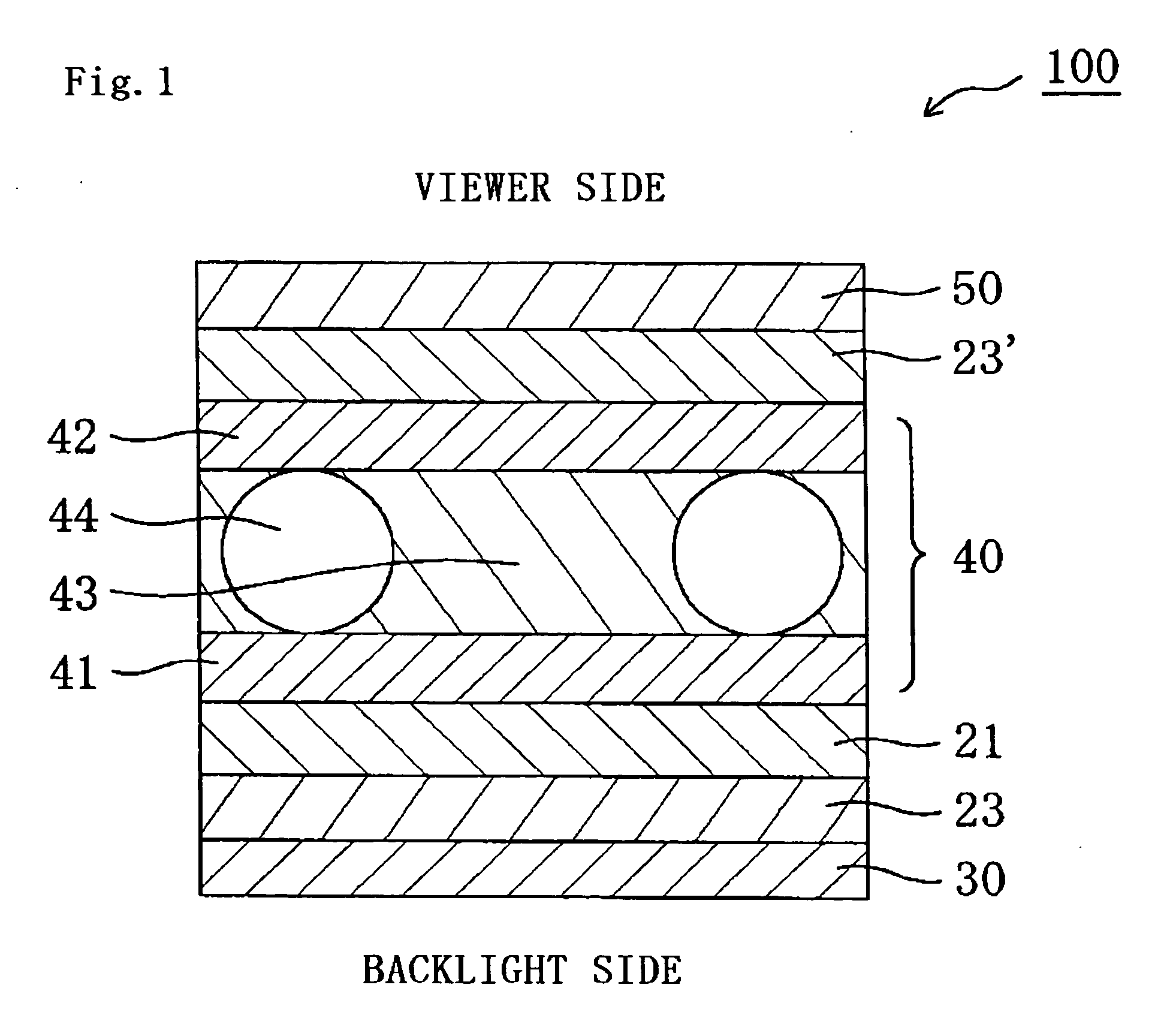
There is provided a liquid crystal panel and a liquid crystal display apparatus each allowing excellent viewing angle compensation and having excellent contrast and small color shift in an oblique direction. The liquid crystal panel of the present invention includes: a first polarizer; a first cellulose-based film; an optical compensation layer having an Nz coefficient represented by an equation (1) of 2≦Nz≦20; a liquid crystal cell; a second cellulose-based film; and a second polarizer in the order given from a backlight side to a viewer side, in which: the first cellulose-based film has a thickness direction retardation (Rth) represented by an equation (2) of 10 nm or less; and the second cellulose-based film has a thickness direction retardation (Rth) represented by the equation (2) of 10 nm or less.
Nz=(nx−nz)/(nx−ny)  (1)
Rth=(nx−nzd  (2)

Description

BACKGROUND OF THE INVENTION [0001] 1. Field of the Invention [0002] The present invention relates to a liquid crystal panel and a liquid crystal display apparatus. The present invention more specifically relates to a liquid crystal panel and a liquid crystal display apparatus each allowing excellent viewing angle compensation and having excellent contrast in an oblique direction and small color shift. [0003] 2. Description of the Related Art [0004]FIG. 7A shows a schematic sectional view of a typical conventional liquid crystal display apparatus, and FIG. 7B shows a schematic sectional view of a liquid crystal cell to be used for the liquid crystal display apparatus. The liquid crystal display apparatus 900 is provided with: a liquid crystal cell 910; retardation plates 920 and 920′ arranged on outer sides of the liquid crystal cell 910; and polarizing plates 930 and 930′ arranged on outer sides of the respective retardation plates 920 and 920′. Typically, the polarizing plates 930 ...

Claims


Application Information

Patent Timeline
IPC IPC(8): G02F1/1335
CPCG02F1/1393G02F1/133634G02F1/1335G02F1/13363
Inventor KIYA, YOSHIYUKIYOSHIMI, HIROYUKIMURAKAMI, NAOTAKEDA, KENTAROU
Owner NITTO DENKO CORP
Why Eureka
Try Eureka