
Method of configuring a cell of a wireless communication system for improved resource utilization

a wireless communication system and cell technology, applied in the field of cell configuration in wireless communication system, can solve the problems of resource demand fluctuation, limit the maximum traffic load that a base station can handle, and resource demand may fluctuate over tim

Active Publication Date: 2006-10-26
ALCATEL LUCENT SAS
View PDF7 Cites 37 Cited by
  • Summary
  • Abstract
  • Description
  • Claims
  • Application Information

AI Technical Summary

Benefits of technology

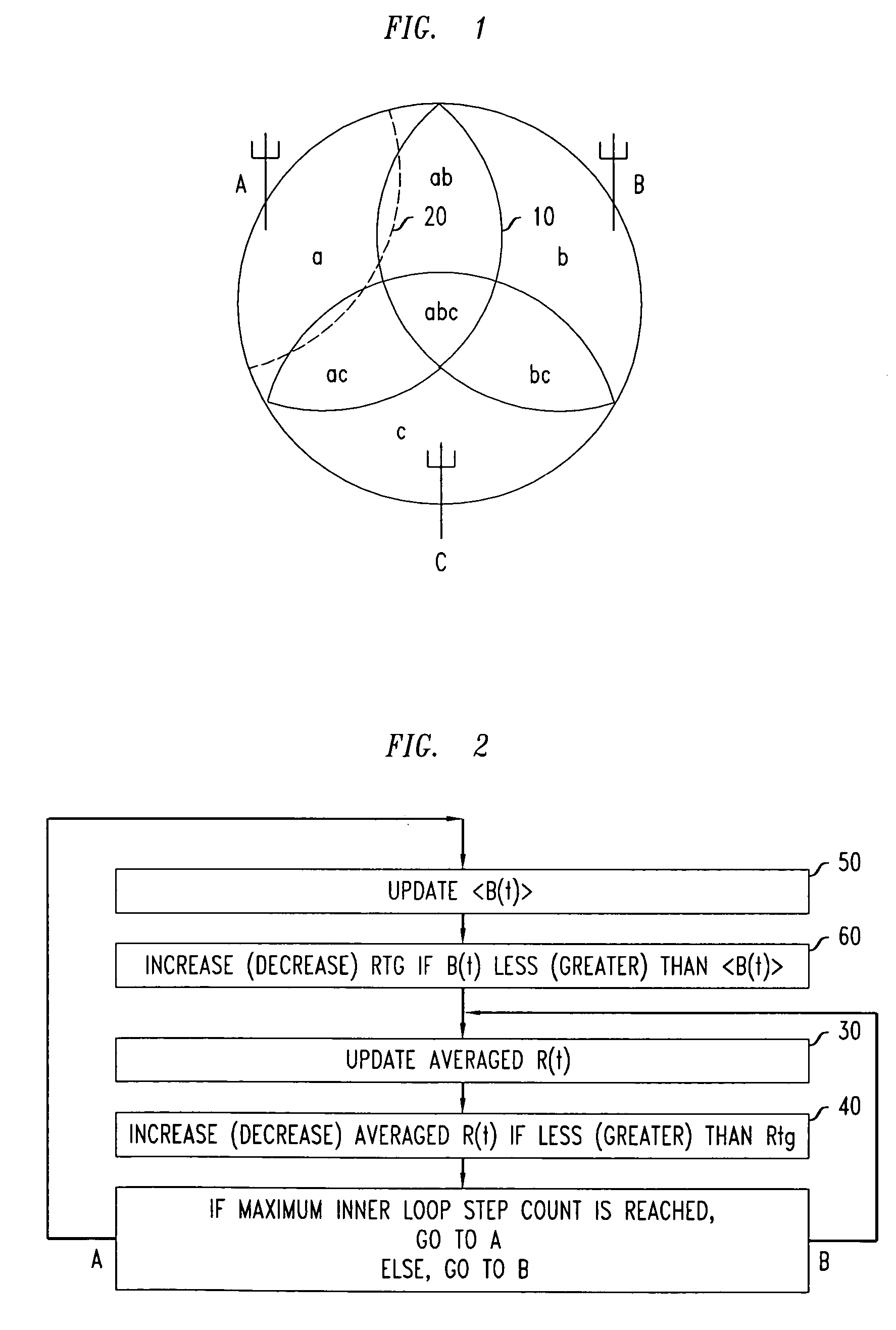
[0017] In certain networks, at least some cells may be sectorized cells. In such cases, we will use the term “cell” to include individual sectors of sectorized cells. Acco

Problems solved by technology

The possibility that one or more cell resources may be fully committed can limit the maximum traffic load that a base station can handle.
User mobility also leads to fading effects which cause resource demand to fluctuate over time.
Moreover, even in a fixed network, resource demand may fluctuate over time due to fading effects and temporal variations in call duration or session duration, and in arrival rate.
As a consequence, there will typically be widespread underutilization of available cell resources.
Because cell resources are expensive, such underutilization is undesirable.
Although useful, such planning tools are limited by the accuracy of their models, and by the fact that it takes weeks or more to implement their prescriptions in an actual network.
Although potentially useful, such approaches suffer the disadvantage that they are complex, slow, and expensive to implement.
However, it suffers from undesirable complexity because of the need for the automata to intercommunicate through the backhaul, and the need for sequential self-sampling by the cells to optimize the power settings.
Sequential self-sampling is slow and subject to the formation of system-wide instabilities.

Method used


Image

  • Method of configuring a cell of a wireless communication system for improved resource utilization
  • Method of configuring a cell of a wireless communication system for improved resource utilization
  • Method of configuring a cell of a wireless communication system for improved resource utilization

Examples


example 1

[0061] Downlink power, but not antenna tilt, is adjusted. We assume that the downlink gain can be made to follow fluctuations in R(t) as rapidly as necessary, and that B(t) can be estimated from R(t) in predictive fashion. This makes it possible to set Rtg to a fixed value, as will be seen below.

[0062] Suppose that R(t) measures the number of trunk-equivalent properties utilized by the cell, such as channel elements, frequencies, or packet pipes. Then the probability for B(t), representing the rate at which access is blocked, can be derived from R(t) through a stochastic model, b:

Pr(B(t))=b(R(t)).

Rtg can be derived from the inverse function of b through:

Rtg=b−1(Bmax).

[0063] As a result, the long term average of the access blocking rate B(t) will remain at or below Bmax if the downlink gain controller succeeds in maintaining R(t) at or below Rtg. An algorithm for that purpose can be implemented in the following fashion:

[0064] If (R(t)

[0065] Otherwise G(t...

example 2

[0067] Downlink power, but not antenna tilt, is adjusted.

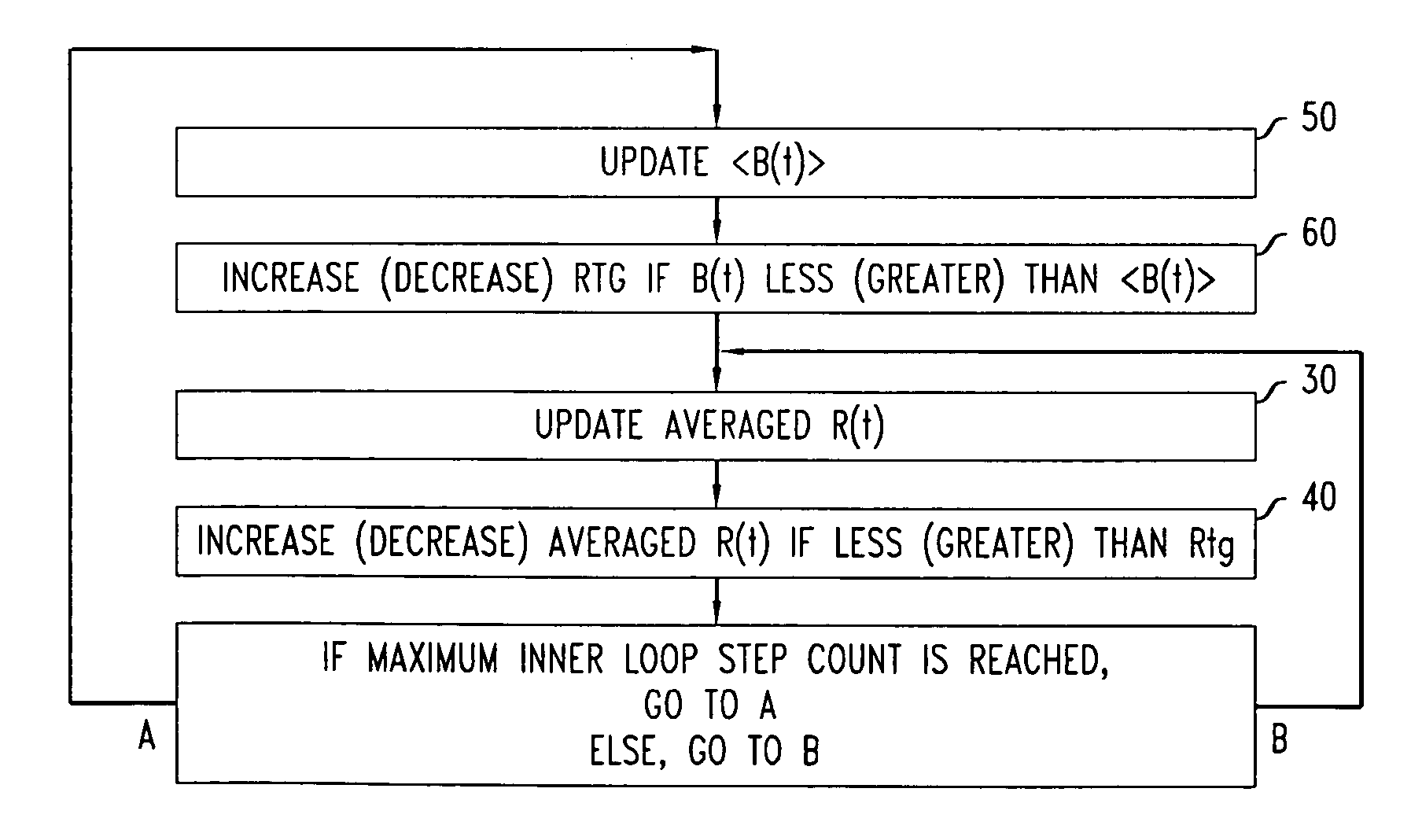
[0068] We drop the assumption that the response time of the gain control is short enough to allow for effectively instantaneous responses to changes in R(t). Moreover, we allow for the possibility that the amplitude of fluctuations in R(t) may change in an unpredictable fashion over time. We here describe a gain control algorithm, to be used under such less idealized conditions, for maintaining the long-term expectation value at or below Bmax. Rtg is now a function Rtg(t) of time.

[0069] The algorithm has two embedded loops: an inner loop and an outer loop. The inner loop adjusts the downlink gain to follow the time-dependent target value Rtg(t). This inner loop can be implemented as a proportional / integral control.

[0070] As shown in FIG. 2, R(t) is averaged at block 30 with some time constant, and adjusted toward Rtg(t) at block 40.

[0071] The outer loop measures B(t) and sets the target Rtg(t) so that the expectation valu...

example 3

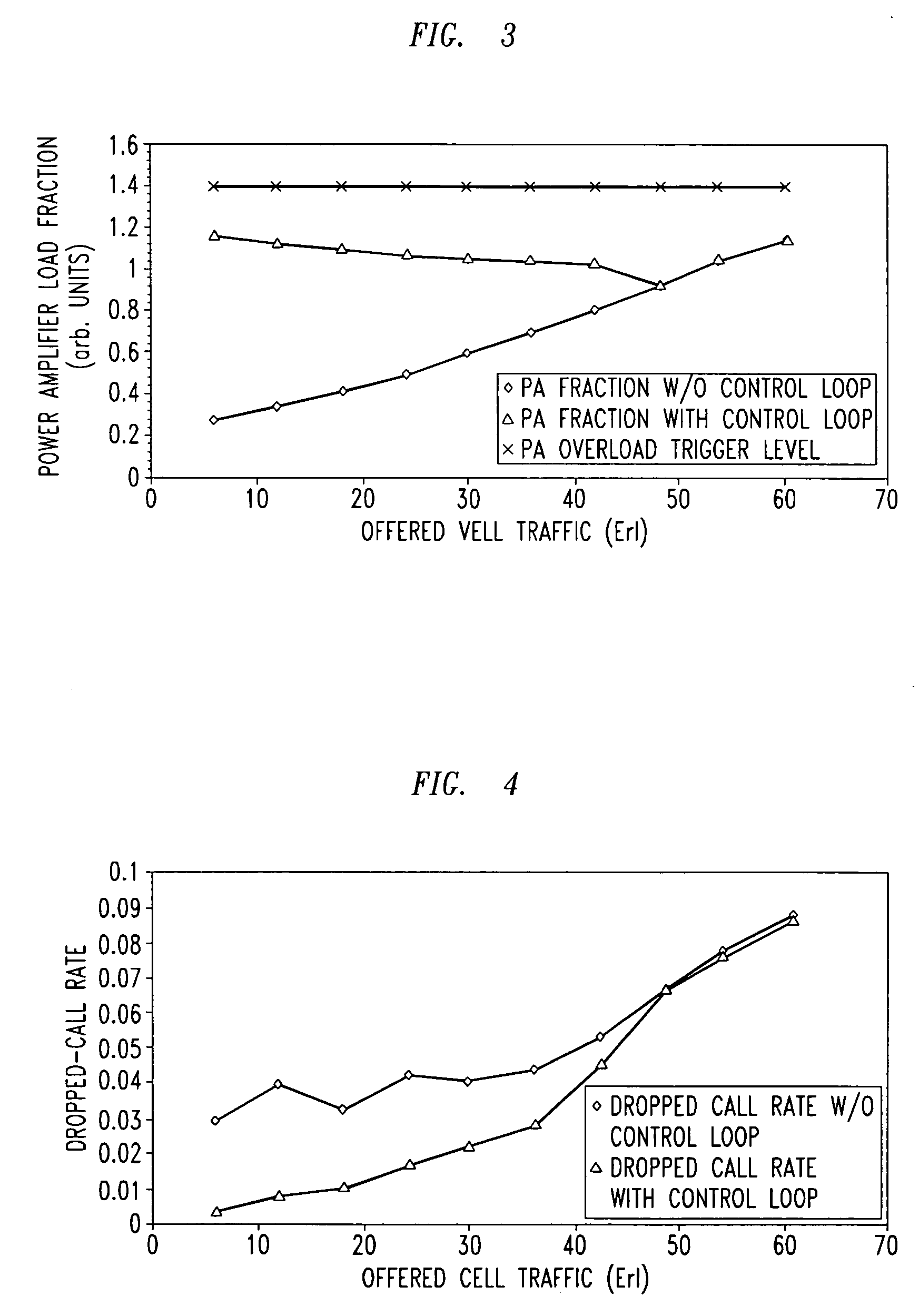
[0075] This is a specific implementation of Example 2, in which R(t) represents the downlink PA power. The quantity R(t) can already be a time-averaged quantity with averaging time T0. This averaging time could, for instance, be set slightly below the inner-loop power control response time (0.667 msec for UMTS, 1.25 ms for 3G1x). In that case, power fluctuations caused by power control would still be captured, whereas faster fluctuations, due, e.g., to baseband code combining, would have been filtered out.

[0076] Rmax represents the upper bound the PA has been rated for with respect to fluctuations over time scales of T0. B(t) can measure an excess of R(t) over Rmax (referred to here as “overswing”) and Bmax can represent the margin within which B(t) is to be maintained over the long term. (Thus, R(t), Rtg(t), and Rmax may all be defined with respect to at least one property of an aggregate downlink transmit power level, which in this example may be a time-averaged power level.)

[00...


PUM


Abstract

At least one base station of a wireless network adjusts its access area so as to drive at least one measure of utilization of a resource or resources of that cell toward, but not to exceed, a specified maximum level. The adjustment is dynamic in that it responds in real time to traffic fluctuations. The adjustment is autonomous in that it is not directed from outside the cell. The access area of the cell is determined by the received strength, at the respective users, of a beacon channel transmitted from the base station. In specific implementations, the access area may be adjusted by adjusting the effective signal transmit strength of the beacon signal, or by adjusting the tilt of the antenna that transmits to the cell.

Description

FIELD OF THE INVENTION [0001] The invention relates to the configuring of cells in wireless communication systems. More particularly, the invention relates to methods aimed at optimizing the performance of cellular networks through adjustment of cell-access areas. ART BACKGROUND [0002] In a typical cellular network, a plurality of base stations are distributed over a target coverage area. A backhaul network connects the base stations to a central node which may, for example, include a radio network controller (RNC) or base station controller (BSC). Wireless users, for example mobile users, communicate with the base stations through the wireless air interface. [0003] Each base station applies certain resources to the processing and transmission of communication traffic. These resources may include access channels, channel codes, spreading codes, packet pipes, time slots, and forward link power, among other things. Such resources are referred to here as “cell resources.”[0004] It will...

Claims


Application Information

Patent Timeline
IPC IPC(8): H04Q7/00H04W16/04
CPCH04W16/04
Inventor BORST, SIMON C.FLANAGAN, MICHAEL J.HAMPEL, KARL GEORG
Owner ALCATEL LUCENT SAS
Learn More