Edge smoothness with low resolution projected images for use in solid imaging

Active Publication Date: 2006-10-26
3D SYST INC
17 Cites 91 Cited by

AI-Extracted Technical Summary

Problems solved by technology

Such systems have encountered and had to overcome difficulties relating to shrinkage, curl and other distortions, as well as resolution, accuracy, and difficulties in producing certain object shapes.
Attempting to utilize image displacement techniques with digital image projections in solid imaging applications presents unique problems because of the three-dimensional aspect of the object being created.
The problems of two-dimensional digital image projection, when ap...

Benefits of technology

[0015] It is an advantage of the present invention that a low cost solid imaging device is obtained that provides high resolution.
[0016] It is another advantage of the present invention that accurate feature placement in each cross-section in a three-dimensional object being built layer-by-layer is obtained so that accurate feature placement is not lost due to the fixed number of pixels that can be projected in a single image projection by a digital light projector.
[0017] It is still another advantage of the present invention that edge filling is accomplished to provide smooth edges...

Abstract

A solid imaging apparatus and method employing sub-pixel shifting in multiple exposures of the digitally light projected image of a cross-section of a three-dimensional object on a solidifiable liquid medium. The multiple exposures provide increased resolution, preserving image features in a three-dimensional object and smoothing out rough or uneven edges that would otherwise be occur using digital light projectors that are limited by the number of pixels in an image projected over the size of the image. Algorithms are used to select pixels to be illuminated within the boundary of each image projected in the cross-section being exposed.

Application Domain

Additive manufacturing apparatusCharacter and pattern recognition +3

Technology Topic

Projection imageImaging Feature +5

Image

  • Edge smoothness with low resolution projected images for use in solid imaging
  • Edge smoothness with low resolution projected images for use in solid imaging
  • Edge smoothness with low resolution projected images for use in solid imaging

Examples

  • Experimental program(1)

Example

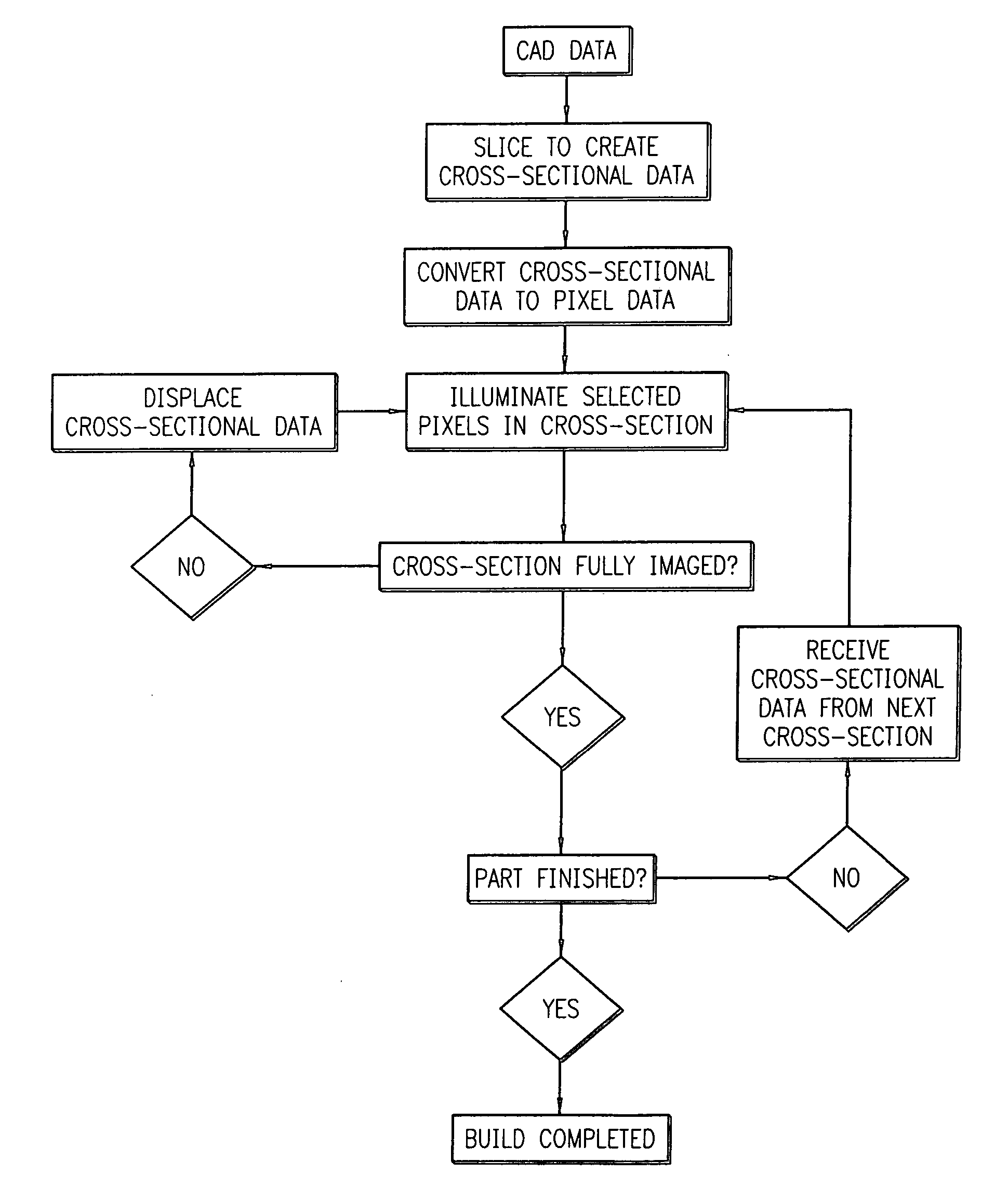
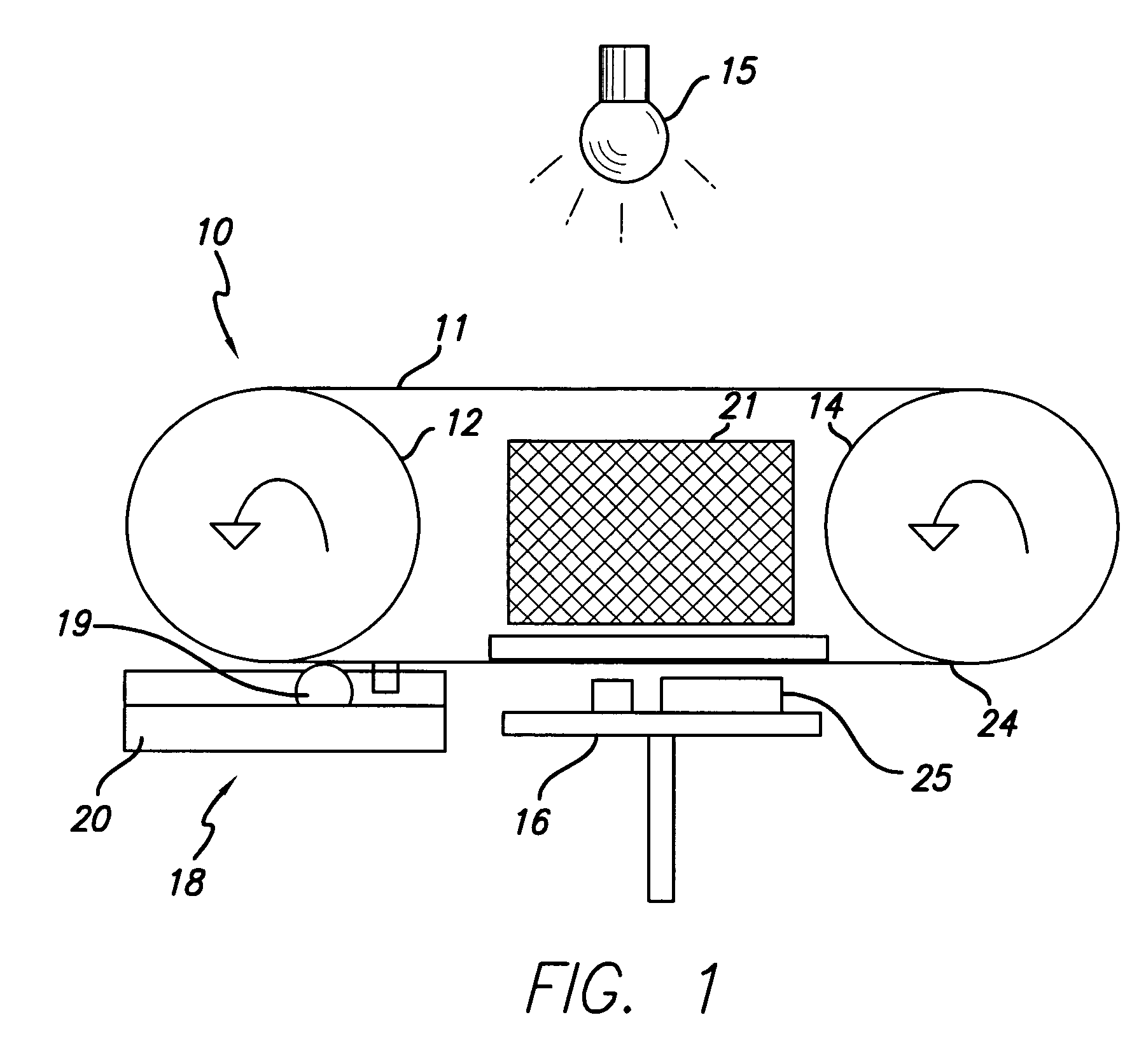
[0025] Flexible transport solid imaging of the type disclosed herein involves the layer-by-layer build-up of articles from a visible or UV liquid photopolymer material that is delivered by the flexible transport endless belt or reciprocatable sheet of film. Liquid photopolymer material is applied to the endless belt or reciprocatable sheet of film from a cartridge employing a gravure wheel that picks up the photopolymer and transfers it to the flexible transport device to provide a fresh material to create new layers as the object is built. The photopolymer is imaged by radiation projected from either a digital UV projector or a digital visible light projector. The projector includes spatial light modulator, such as a digital micro-mirror device (“DMD”), that selectively illuminates pixels for imaging. Visible light projection is a preferred approach.
[0026] Solid imaged parts are preferably built on an elevator platform that moves the build object or part up into contact with the liquid photopolymer and, after exposure, down and out of contact with the liquid photopolymer as successive layers or laminae are formed during the building process. The build object can be built on structures known as supports rather than directly on the elevator platform. Supports are used for more complex three-dimensional objects being built that have unsupported or partially unsupported surfaces.
[0027] Commercially available digital light projectors, optionally modified to have a shorter focal length, may be employed, such as those available from InFocus Corporation of Wilsonville, Oreg. and BenQ America Corp. of Irvine, Calif. However, digital light projectors inherently have limited resolution. For example, if a 1024 by 768 pixel image is projected over a 10.24 inch by 7.68 inch area the effective resolution is 100 dpi (100 dots per inch). In this case the minimum feature size is 0.010 inch, part features may be located as far off their correct position as 0.005 inch, and a wall drawn at 45° to the X or Y axis will have a peak to peak roughness of 0.007 inch. Also, walls along the X and Y axes will exhibit roughness.
[0028] Sub-pixel image shifting is a way to improve accuracy and edge smoothness in three-dimensional objects crated by solid imaging. This approach is based on exposing a full sized image, and then shifting the image plane half a pixel or less, adjusting the projected image to match the new image position, and then exposing again. With this technique, and shifting half a pixel in the X and Y planes, the 10.24 inch by 7.68 inch area described above would look like it had an effective resolution of 200 dpi. If the image is shifted twice at one third of a pixel, and exposed three times, it has an effective resolution of 300 dpi, etc. In these cases the accuracy and the wall smoothness of the solid image or three-dimensional object built are improved.
[0029] In one application of the present invention, the photopolymer material is delivered to the imaging area via a transparent flexible transport film such as polypropylene or polycarbonate. The photopolymer is applied in a thin layer to the flexible transport film in the embodiment shown in FIG. 1.
[0030] As seen in FIG. 1, a flexible transport imaging system indicated generally by the numeral 10, has a transparent transport means in the form of an endless belt 11 that is positioned about a driving roller 12 and a follower roller 14. A digital light projector is the light source 15 that projects an image with selected pixels for illumination onto a mirror ((not shown) below the upper run of endless belt 21 in the exposure of a cross-section of a three-dimensional object 25 being formed on a support platform 16. Support platform 16 is raised and lowered to bring the cross-sectional layers being formed into contact with the layer of build material 24 that is deposited on endless belt 11 from the resin or solidifiable liquid medium cartridge indicated generally by the numeral 18. Cartridge 18 includes a resin reservoir of solidifiable liquid medium 20 and a gravure roller 19 that applies the solidifiable liquid medium to belt 11. A transparent backing plate 22 can be employed. A sub-pixel image placement device, indicated generally by the numeral 21, is placed between the light source 15 and the target area on the belt 11 that is coated with the solidifiable liquid medium 24. The exposure of the image cross-section by illuminating selected pixels creates a solidified portion of the cross-section of the three-dimensional object being formed. Device 21 alternatively can be a mirror with the pixel shifting device being located outside of the runs of the endless belt 21 or it could combine both the mirror and the pixel shifting device in a single element.
[0031] Looking now at FIG. 2, there is shown in a diagrammatic illustration of one embodiment of a pixel image displacement device that can be employed in a solid imaging system to create solid objects by successively creating thin layers of a solidified material one on top of the other by use of a digital light projector light to selectively illuminate pixels on the surface of a solidifiable liquid medium. FIG. 2 shows a digital light projector 26 projecting an image through a transparent plate 28 rotatable about a fixed point 27 onto the image plane 29 on the surface of a solidifiable liquid medium to form a cross-section of a three-dimensional object. The plate 28 can be a glass plate that is mounted on a two axis mirror mount to displace by a fraction of a pixel the pixels in a projection of a full image of the cross-section of a three-dimensional object. The plate 28 is moved through a tilt angle {circle around (−)} that determines the amount of pixel displacement. In this embodiment, by way of example, the relationship between the tilt angle ({circle around (−)}) of the glass plate and the displacement in the image plane (d) is given by the equation:
d=l cos {circle around (−)}[tan {circle around (−)}−tan (asin(sin {circle around (−)}/n))]
where l is the thickness of the glass and n is the index of refraction.
[0032]FIG. 3 gives a graphical illustration showing this displacement for the case of n=1.5 and l=4.35 mm. A tilt angle of 5° corresponds to a shift of ½ pixel for a 4 pixels per mm image.
[0033]FIG. 4 shows the flow diagram of the process employed to create a three-dimensional object using the process and apparatus of the present invention.
[0034] Data is sent to the solid imaging system from a CAD station (not shown) that converts the CAD data to a suitable digital layer data format and feeds it to a computer control system (also not shown) where the object data is manipulated to optimize the data via an algorithm to provide on/off instructions for the digital light projector. The solid imaging layer data is attained by the CAD data being processed by a slicing program to create cross-sectional data. The algorithm is then applied to the cross-sectional data by a suitable controller, such as a microprocessor or computer, to create the instructions for the digital light projector to illuminate selected pixels in the image within the boundary of the three-dimensional object in the cross-section being formed. The algorithm can select pixels for illumination that are only full pixels within the boundary of the image in the cross-section being exposed as seen in FIGS. 5A-C. FIG. 5A illustrates a first exposure of a cross-sectional layer. FIG. 5B illustrates a second exposure of the same cross-sectional layer with the pixels shifted in the X and y directions. FIG. 5C is the resultant exposure on the same cross-sectional layer of the two exposures illustrated in FIGS. 5A and 5B. Alternatively as desired, the algorithm can select as pixels for illumination only those pixels having a desired percentage, ranging from about 1% to about 100%, of the full pixel within the boundary of the image in the cross-section being exposed depending upon the number of exposures and pixel shifts to be done within each cross-section. For example, if only two exposures and hence only one pixel shift is to be done in each cross-section, it is desirable to illuminate only those pixels that have a lower percentage of the full pixel within the boundary of the image in the cross-section being exposed to increase the covered area, the resolution and edge smoothness of the image. Contrarily, if a higher number of exposures, such as 5 and hence 4 pixel shifts, is to be done in each cross-section, then illumination of only those pixels having a higher percentage of the full pixel within the boundary of the image would occur. Additionally, the algorithm may factor in the area of the pixel within the boundary of the image in the cross-section separately or in combination with a selected angle that the image boundary goes through the pixels within the image in the cross-section being exposed. At some desired percentage of pixels within the boundary of the cross-section being exposed, the image will be larger than desired. In this instance some “line width correction” of the cross-section's boundary will be required. Where supports are used in the build process, either with two separate materials or one material that is the same for the build object and the supports, no pixel shifting or second exposure in each support cross-section is utilized in a second support generating algorithm and any pixel having any portion of a support within the boundary of the image is illuminated.
[0035] As seen in FIG. 4, the cross-sectional data, including boundary and fill data for the object, is converted to pixel data and then processed to determine which selected pixels are to be illuminated as they fall within the boundary of the image in the cross-section be exposed. After the first exposure, the cross-sectional data is displaced by the desired sub-pixel distance and the cross-section is again illuminated with selected pixels. If the cross-section is full imaged, the process then returns to receive cross-sectional data from the next cross-section and the process is continued until a three-dimensional object is completed. Alternatively, if the cross-section is not full imaged, the cross-sectional data is displaced and selected pixels are illuminated in a process that continues until the cross-section is full imaged.
[0036] As previously stated, either an ultraviolet (“UV”) digital radiation projector or a visible digital light projector system may be used to cure the photocurable solidifiable liquid medium. With either type of a digital light projector, an algorithm that selects out pixels in a cross-section that have previously been exposed can be employed to prevent overcuring of the resin in those areas. Such overcuring can cause part curl, shrinkage and part distortion. Additionally, it is possible to convert the image boundaries to a bit map and then shift only those pixels that contain the boundaries to obtain the required sub-pixel placement accuracy edge smoothness.
[0037] Any suitable fluid medium capable of solidification in response to the application of an appropriate form of energy stimulation may be employed in the practice of the present invention. Many liquid state chemicals are known which can be induced to change to solid state polymer plastic by irradiation with UV radiation or visible light. A suitable visible visible light curable photopolymer that may be employed in the practice of the present invention is shown in Table I below. This formulation exhibited excellent resolution and photospeed when utilized with a BenQ PB7220 projector. The parts created displayed outstanding green strength with balanced stiffness and toughness. TABLE 1 Units of Weight Weight Percent Acrylate-24 (from Sartomer Company) % PRO 6817 (from Sartomer Company) 4.8 23.02 SR 833S (from Sartomer Company) 3.5 16.79 Ebecryl 83 (from UCB Chemicals Corp.) 2.4 11.51 PRO 6169 (from Sartomer Company) 5.2 24.94 SR 531 (from Sartomer Company) 3.6 17.27 Irgacure I-907 (From Ciba Specialty 0.75 3.60 Chemicals, Inc.) Irgacure I-819 (From Ciba Specialty 0.6 2.88 Chemicals, Inc.) Total 20.85 100.00
Additives can be incorporated into the formulation to promote release ability from the transparent transport means, such as silicone acrylate materials.
[0038] Alternatively, the image projected onto the solidifiable liquid medium for solid imaging an object can be shifted by rotating or otherwise moving the image shifting mirror or by physically moving the cross-section being built.
[0039] While the invention has been described above with references to specific embodiments thereof, it is apparent that many changes, modifications and variations in the materials, arrangements of parts and steps can be made without departing from the inventive concept disclosed herein. For example, the sub-pixel image displacement technique could equally well be employed in a modified stereolithography apparatus having a vat employing a UV or visible digital light projector in place of a laser. An example of such a stereolithography apparatus that could easily be modified is a Viper si2™ SLA® system available commercially from 3D Systems, Inc., the assignee of the present invention. The sub-pixel image displacement device employs at least one rotatable transparent plate as described herein, rotatable mirrors, shiftable digital light projectors or a shiftable support platform to displace the pixels in the image of a projected cross-section of a three-dimensional object being formed from a solidifiable liquid medium. The liquid medium forms a fresh layer to be solidified either by a deep dip technique or by use of a recoater that places a fresh layer of liquid material onto an already exposed and solidified cross-section of the three-dimensional object being formed, as described in U.S. Pat. Nos. 5,902,537 and 6,048,487 both assigned to the assignee to the present invention. Accordingly, the spirit and broad scope of the appended claims are intended to embrace all such changes, modifications and variations that may occur to one of skill in the art upon a reading of the disclosure. All patent applications, patents and other publications cited herein are incorporated by reference in their entirety.

PUM

PropertyMeasurementUnit
Fraction
Angle
Size

Description & Claims & Application Information

We can also present the details of the Description, Claims and Application information to help users get a comprehensive understanding of the technical details of the patent, such as background art, summary of invention, brief description of drawings, description of embodiments, and other original content. On the other hand, users can also determine the specific scope of protection of the technology through the list of claims; as well as understand the changes in the life cycle of the technology with the presentation of the patent timeline. Login to view more.

Similar technology patents

Magnetically guided catheter

ActiveUS20100174177A1low costhigh performance
Owner:ST JUDE MEDICAL ATRIAL FIBRILLATION DIV

Head mounted display with eye accommodation

InactiveUS20070097277A1low cost
Owner:UNIV OF CENT FLORIDA RES FOUND INC +1

Method for removing pollutants in sewage

InactiveCN103449680Alow costEasy to prepare
Owner:JIANGSU LV CHUAN ENVIRONMENTAL PROTECTION TECH

Classification and recommendation of technical efficacy words

  • high resolution
  • low cost

Imaging optical lens assembly

ActiveUS8000031B1high resolutionreduce total track length
Owner:LARGAN PRECISION

Scanning mechanisms for imaging probe

ActiveUS20080177138A1high resolution
Owner:SUNNYBROOK HEALTH SCI CENT

System, apparatus and method for biomedical wireless pressure sensing

InactiveUS20090299216A1high resolutionreliable pressure measurement
Owner:CALIFORNIA INST OF TECH

System and method for transmitting wireless digital service signals via power transmission lines

ActiveUS7929940B1reduce bandwidth requirementlow cost
Owner:NEXTEL COMMUNICATIONS

Plastic waveguide-fed horn antenna

InactiveUS20100214185A1low cost
Owner:RGT UNIV OF CALIFORNIA

System and method for determination of position

InactiveUS20090149202A1low costreduce requirement
Owner:STEELE CHRISTIAN

Adaptive antenna optimization network

InactiveUS6961368B2low costminimal space
Owner:ERICSSON INC
Why Eureka
Try Eureka