Carriage driving apparatus and Image reading apparatus and image recording apparatus using the same

a technology of image reading apparatus and carriage driving apparatus, which is applied in the direction of printing mechanisms, instruments, printing, etc., can solve the problems of undesirable employment of ccd in the image reading apparatus, push up the cost of the carriage driving apparatus, and so as to prevent the disengagement of the timing belt from the driven pulley

Active Publication Date: 2006-10-26
BROTHER KOGYO KK
View PDF5 Cites 14 Cited by
  • Summary
  • Abstract
  • Description
  • Claims
  • Application Information

AI Technical Summary

Benefits of technology

[0011] The present invention has been developed in view of the above-described situations, and therefore it is an object of the invention to provide a carriage driving apparatus for reciprocating a carriage on which an image sensor, a recording head, or others is mounted, which apparatus is capable of preventing a timing belt from disengaging from a driven pulley, with a simple structure.
[0013] The pulley holder is movable, under guidance by the guide device, toward the tensioning position or in the tensioning direction to tension the timing belt, which may be referred to as “to the tensioning side”, and toward the slackening position or in the slackening direction to slacken the timing belt, which may be referred to as “to the slackening side”. The slackening position of the pulley holder is such that when the pulley holder is located at this position, the timing belt is allowed to be freely or naturally wound around or disengaged from, the driven pulley. The pulley holder is biased by the biaser held by the biaser holder to the tensioning side in order to tension, with an appropriate tensile force, the timing belt wound around the drive pulley and the driven pulley. Even where the pulley holder or other members deforms due to change in temperature or for other reasons, the pulley holder moves to the tensioning side or to the slackening side and the tensile force of the timing belt is kept constant, with a variation range of the biasing force of the biaser relatively small. Since the biaser holder limits the movement of the pulley holder toward the slackening position, to the disengagement inhibit position at most, even where the carriage greatly moves due to an impact, the pulley holder is inhibited from reaching the slackening position where the timing belt is naturally disengageable from the driven pulley, thereby preventing the timing belt from disengaging from the driven pulley. That is, the disengagement inhibit position of the pulley holder is such that when the pulley holder is located at this position, the timing belt does not naturally disengage from the driven pulley, unless intentionally disengaged by a user or others. In this way, it is enabled to prevent disengagement of the timing belt from the driven pulley with a simple structure.
[0016] According to this arrangement, the biaser and the biaser holder are used to determine the limit of the movement of the pulley holder in the slackening direction, in order to reduce at least one of the number of components and the number of assembly steps. The thus determining the limit of movement of the pulley holder in the slackening direction can prevent, for instance, disengagement of the timing belt from the driven pulley as in the previously described carriage driving apparatus, or disengagement of the pulley holder from the guide device.
[0018] In the image reading apparatus and the image recording apparatus, each of the carriage driving apparatuses constructed as described above makes it possible to prevent disengagement of the timing belt from the driven pulley, with a simple structure. Hence, the number of components of the image reading apparatus or the image recording apparatus as a whole can be reduced, and the efficiency of assembly of the image reading apparatus or the image recording apparatus is enhanced.
[0022] On the other hand, according to the latter method, the biaser is first attached to the biaser holder, and then the timing belt is forcibly wound around the pulley holder with a relatively large tensile force applied to the timing belt in the tensioning direction while the pulley holder is held at the disengagement inhibit position. However, once the carriage driving apparatus is finished as a product, such a large tensile force in the tensioning direction that enables disengagement of the timing belt from the driven pulley is not naturally applied to the timing belt, unless intentionally applied by a user. Thus, disengagement of the timing belt from the driven pulley is prevented.

Problems solved by technology

The increase in the number of components and assembly steps pushes up the cost of the carriage driving apparatus.
However, when an impact is imposed on the carriage driving apparatus to displace the carriage by a large amount, during transportation of the machine or in other situations, the pulley holder may greatly slide in the direction to slacken the timing belt against the biasing force of the compression spring, resulting in disengagement of the timing belt from the driven pulley, or disengagement of the pulley holder from the guiding slot.
However, employment of the CCD in the image reading apparatus is undesirable since the cost and size of the image reading apparatus increase.
However, when the carriage driving apparatus includes neither the restrictor that limits sliding movement of the pulley holder, nor the retainer that temporarily fixes the carriage to the base of the machine to prevent displacement of the carriage, the timing belt or the pulley holder may disengage during transportation of the machine or in other situations, as described above.

Method used


Image

  • Carriage driving apparatus and Image reading apparatus and image recording apparatus using the same
  • Carriage driving apparatus and Image reading apparatus and image recording apparatus using the same
  • Carriage driving apparatus and Image reading apparatus and image recording apparatus using the same

Examples


Embodiment Construction

[0039] Hereinafter, there will be described presently preferred embodiments of the invention, by referring to the accompanying drawings.

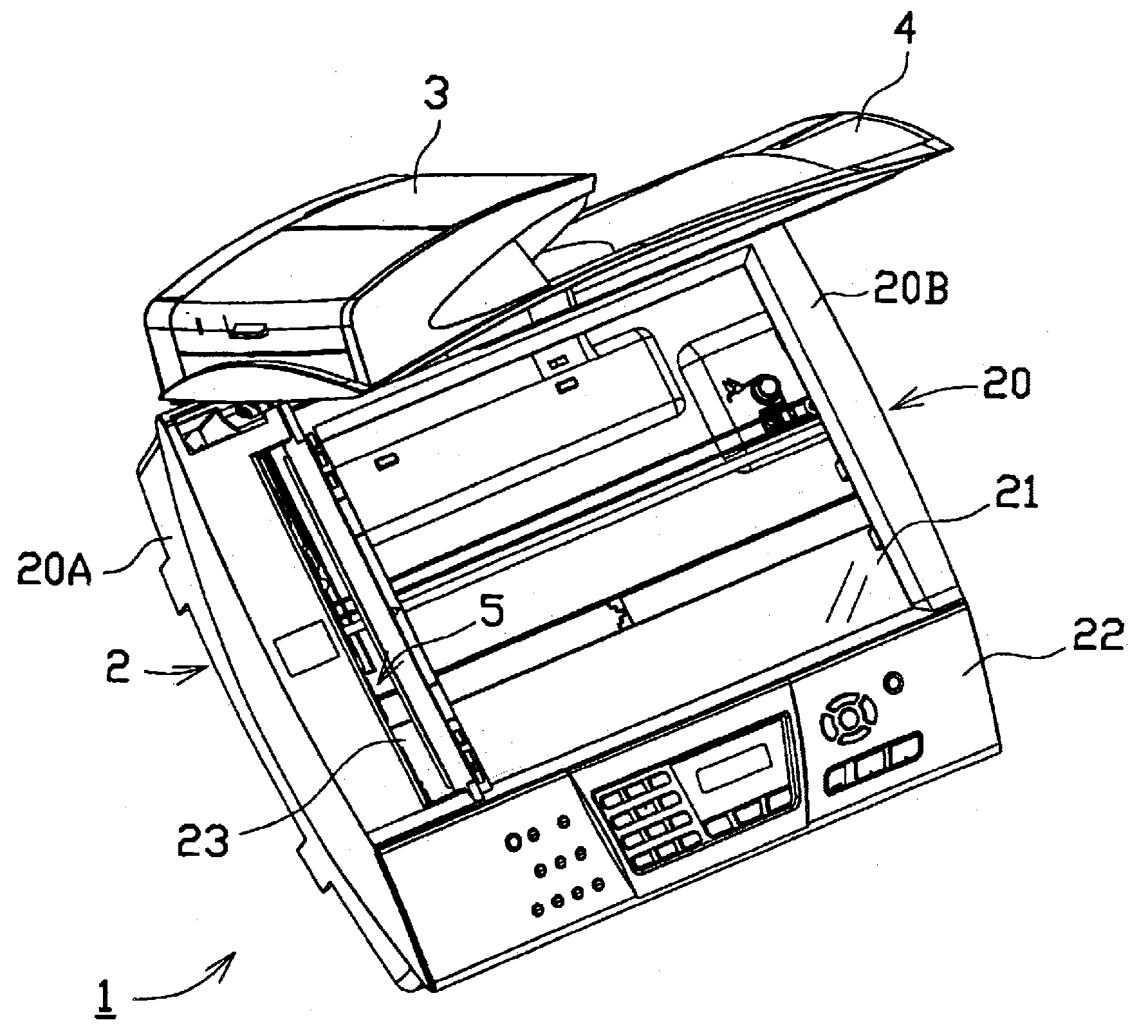
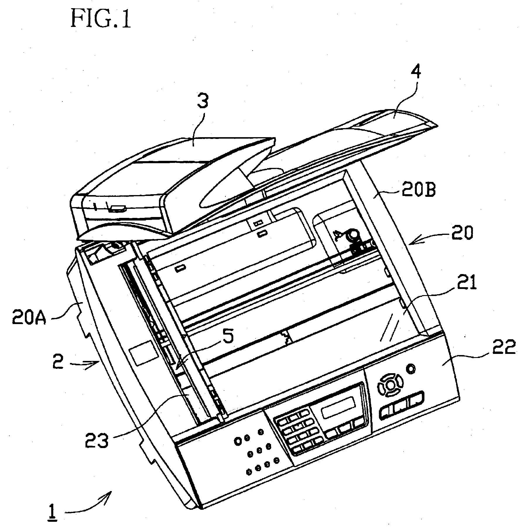
[0040] First, an image reading apparatus according to a first embodiment of the invention will be described by referring to FIGS. 1-10. In FIG. 1, reference numeral 1 generally denotes an image reading apparatus according to the first embodiment. For instance, the image reading apparatus 1 may be used as a scanner of an MFD (Multi Function Device) that integrally includes a plurality of functions such aspringer function and scanner function, or may be used as an image reading apparatus of a copy machine. That is, the image reading apparatus 1 of the invention may or may not be integrated with another function. Namely, the image reading apparatus 1 may be implemented as a FBS (flatbed scanning machine) having only scanner function. In each of the embodiments described below, a carriage driving apparatus of the present invention is applied to an imag...


PUM


Abstract

There is disclosed a carriage driving apparatus for reciprocating, along a straight line, a carriage by a timing belt wound around at least a drive pulley and a driven pulley. The apparatus includes: a pulley holder which holds the driven pulley such that the driven pulley is rotatable; a guide device which guides the pulley holder such that the pulley holder is movable at least between a slackening position where engagement and disengagement of the timing belt with and from the driven pulley is allowed, and a tensioning position where the timing belt is tensioned; a biaser which biases the pulley holder in a tensioning direction to tension the timing belt; and a biaser holder which holds the biaser such that the pulley holder is allowed to move to the slackening position when the biaser is not held by the biaser holder, and the pulley holder is biased by the biaser in the tensioning direction when the biaser is held by the biaser holder, the biaser holder limiting movement of the pulley holder in a slackening direction to slacken the timing belt, to a disengagement inhibit position between the slackening position and the tensioning position.

Description

INCORPORATION BY REFERENCE [0001] The present application is based on Japanese Patent Application No. 2005-036147, filed on Feb. 14, 2005, the content of which is incorporated herein by reference. BACKGROUND OF THE INVENTION [0002] 1. Field of the Invention [0003] The invention relates to a carriage driving apparatus for reciprocating a carriage by a timing belt wound around a drive pulley and a driven pulley. The invention also relates to an image reading apparatus and an image recording apparatus including such a carriage driving apparatus. [0004] 2. Description of Related Art [0005] As an image reading apparatus in a copy machine and a multifunction machine, there is known a flatbed scanner having a reading table in which is disposed a carriage on which an image sensor such as CCD (Charge Coupled Device) or CIS (Contact Image Sensor) is mounted in order to scan or read an image on a document placed on the reading table. As a carriage driving apparatus for reciprocating the carria...

Claims


Application Information

Patent Timeline
Patent Type & Authority Applications(United States)
IPC IPC(8): F16H7/14F16H7/08F16H7/12
CPCB41J19/005F16H2007/081F16H2007/0806F16H7/1263
Inventor OSAKABE, YOSHINORIOHAMA, TAKASHI
Owner BROTHER KOGYO KK
Why Eureka
Try Eureka