Spinal implant

a technology of artificial fusion and spinal implants, which is applied in the field of artificial fusion implants, can solve the problems of significant infection risk, less bone use, damage to nerves, etc., and achieve the effects of less blood loss, enhanced safety, and greater simplicity

Inactive Publication Date: 2006-10-26
WARSAW ORTHOPEDIC INC
View PDF33 Cites 144 Cited by
  • Summary
  • Abstract
  • Description
  • Claims
  • Application Information

AI Technical Summary

Benefits of technology

[0046] The present invention comprises an artificial implant, the purpose of which is to participate in, and directly cause bone fusion across an intervertebral space following .the excision of a damaged disc. Said implants are structurally load bearing devices, stronger than bone, capable of withstanding the substantial forces generated within the spinal interspace. Such devices have a plurality of macro sized openings of 13 mm, which can be loaded with fusion promoting materials, such as autogenous bone, for the purpose of materially influencing the adjacent vertebrae to perform a bony bond to the implants and to each other. The implant casing may be surface textured or otherwise treated by any of a number of known technologies to achieve a “bone ingrowth surface” to further enhance the stability of the implant and to expedite the fusion. Further, said devices are so configured and designed so as to promote their own stability within the vertebral interspace to resist dislodgement, and furthermore, to stabilize the adjacent vertebrae.
[0050] It is another object of the present invention to provide for a means of achieving an interspace fusion and stabilization that is quicker, safer, and entails less blood loss than by any other known means.
[0051] It is another object of the present invention to provide for a means of achieving a one stage interspace fusion and stabilization without significant violation or removal of the adjacent vertebral bone stock.
[0052] It is another object of the present invention to provide for a method of intervertebral arthrodesis and stabilization of enhanced safety where the entire procedure is performed under direct vision.
[0053] It is another object of the present invention to provide for a method of intervertebral arthrodesis and stabilization of greater simplicity and requiring minimal specialized instrumentation or technique not already possessed by those doing such procedures by conventional means.

Problems solved by technology

If nothing is placed in the space the space may collapse which may result in damage to the nerves; or the space may fill with scar tissue and eventually lead to a reherniation.
The use of bone is less than optimal in that the bone obtained from the patient requires additional surgery and is of limited availability in its most useful form and if obtained elsewhere, lacks living bone cells, carries a significant risk of infection, and is also limited in supply as it is usually obtained from young accident victims.
Furthermore, regardless of the source of the bone, it is only marginal structurally and lacks a means to either stabilize itself against dislodgement, or to stabilize the adjacent vertebrae.
No such device has been found that is medically acceptable.
While the present invention is to be placed within the disc space, these prior devices cannot be placed within the disc space as at least one vertebra has already been removed and there no longer remains a “disc space.” Furthermore, all of these devices are limited in that they seek to perform as temporary structural members mechanically replacing the removed vertebra (not a removed disc), and do not intrinsically participate in supplying osteogenic material to achieve cross vertebrae bony fusion.
In summary, none of these devices are designed for or can be used within the disc space, do not replace a damaged disc, and do not intrinsically participate in the generation of a bony fusion.
Such bleeding, when it occurs, bears all the risks of blood loss (e.g. hypovolemic shock, transfusion transmitted diseases such as hepatitis and acquired immune deficiency syndrome, etc.), and all the complications arising from the resultant impaired visualization of the vital structures (e.g. nerves, blood vessels, and organs) due to such bleeding.
Implantation of a single implant of those dimensions from a posterior approach in the lumbar spine would otherwise be impossible because of the presence of the dural sac and spinal nerves.

Method used


Image

  • Spinal implant
  • Spinal implant
  • Spinal implant

Examples


Embodiment Construction

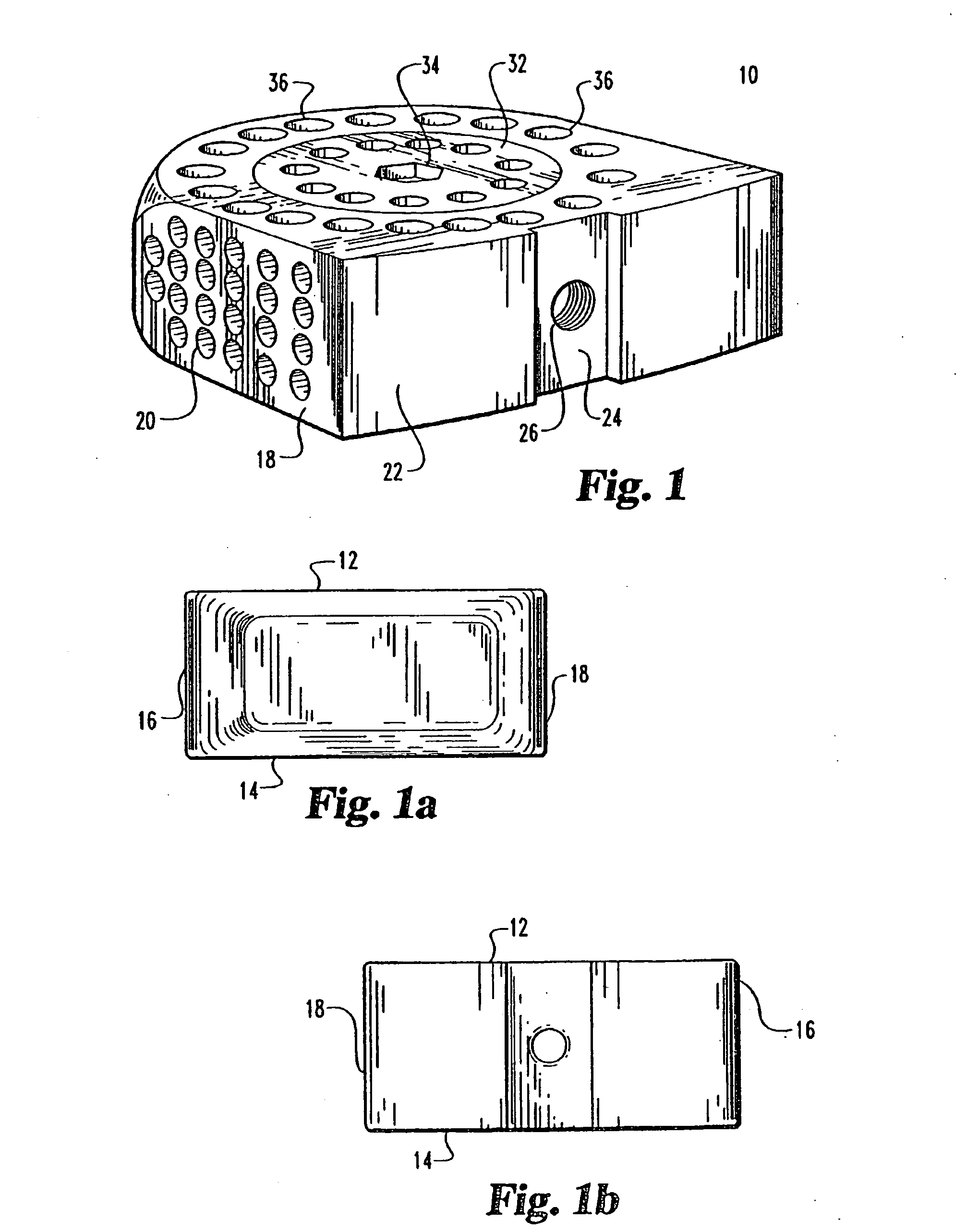
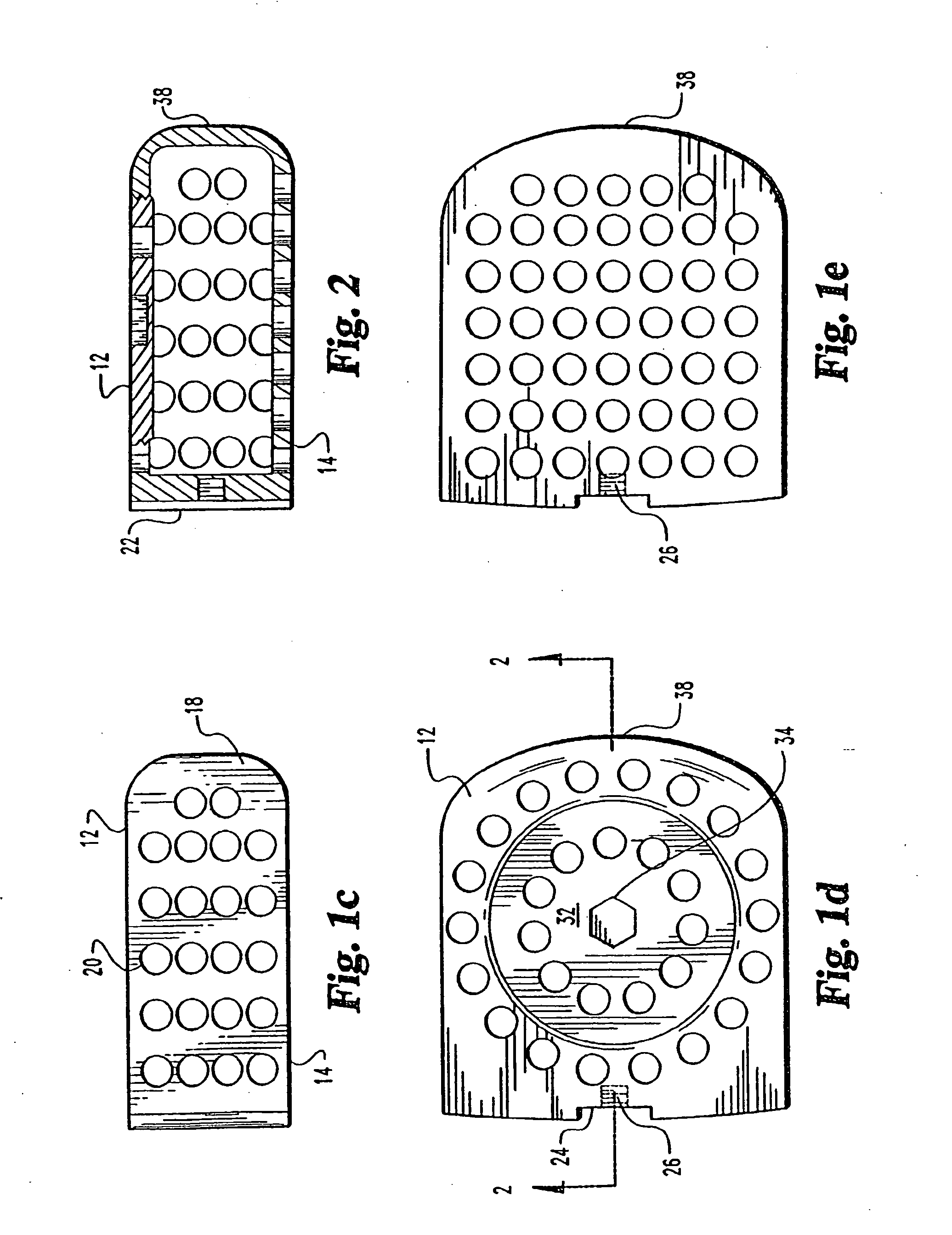
[0082] Referring to FIGS. 1 through 5 an implant for use in the disc space and associated apparatus used for inserting the implant 10 is shown. The implant 10 is shown as a substantially rectangular hollow configuration, having a tapered forward portion.

[0083] The implant 10 has an upper surface 12 and a parallel lower surface 14. The two side walls 16 and 18 are parallel to one another and have a series of small sized openings 20 of 1 mm 3 mm through the side walls 16 and 18.

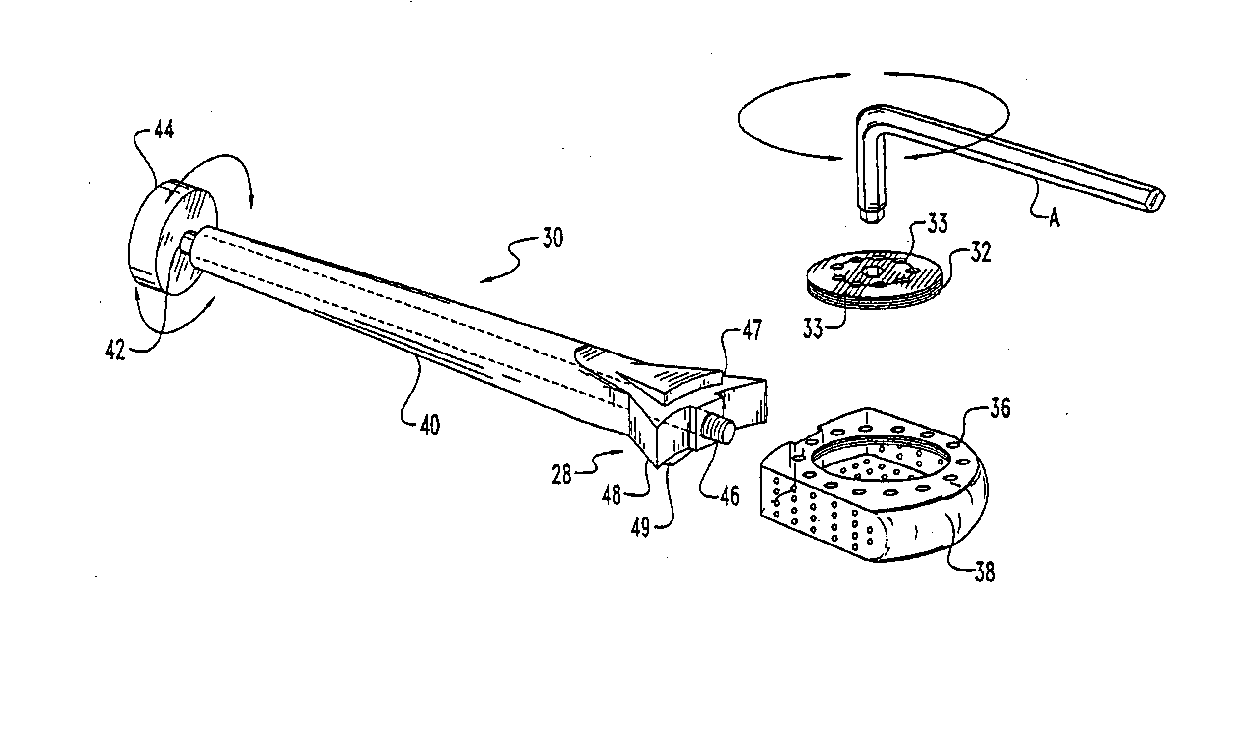
[0084] The front wall 22 is slightly convex and has a depressed portion 24 with a central threaded opening 26 for receiving the engaging end 28 of a driving member 30.

[0085] The upper surface 12 has a threaded cap 32, which has opening 33 there through, with a central wrench opening 34 for engagement with an ALLEN hex key wrench A of FIG. 3. The cap 32 covers the opening into the hollow implant 10 and permits the insertion of autogenous bone material into the hollow portion of the implant 10. The cap 32 is s...


PUM

PropertyMeasurementUnit
widthaaaaaaaaaa
widthaaaaaaaaaa
lengthaaaaaaaaaa

Abstract

A spinal implant is disclosed which when placed within the spinal disc space stabilizes the spinal segment.

Description

[0001] The present application is a continuation of application Ser. No. 10 / 292,539, filed Nov. 12, 2002, now U.S. Pat. No. 7,066,961; which is a continuation of application Ser. No. 09 / 580,768, filed May 30, 2000, now U.S. Pat. No. 6,478,823; which is a continuation-in-part of application Ser. No. 29 / 056,996, filed Jul. 15, 1996, now U.S. Pat. No. D425,989; which is a continuation of application Ser. No. 29 / 023,922, filed Jun. 3, 1994, now abandoned; which is a continuation of application Ser. No. 08 / 052,211, filed on Apr. 22, 1993, now abandoned; which is a continuation of application Ser. No. 07 / 546,849, filed Jul. 2, 1990, now abandoned; which is a continuation of application Ser. No. 07 / 212,480, filed Jun. 28, 1988, now abandoned; all of which are incorporated herein by reference.BACKGROUND OF THE INVENTION [0002] The present invention relates to an artificial fusion implant to be placed into the intervertebral space left after the removal of a damaged spinal disc. [0003] The p...

Claims


Application Information

Patent Timeline
Patent Type & Authority Applications(United States)
IPC IPC(8): A61F2/44A61B17/88A61F2/00A61F2/02A61F2/28A61F2/30A61F2/46
CPCA61F2/30744A61F2310/00796A61F2/44A61F2/442A61F2/4455A61F2/447A61F2/4611A61F2002/2835A61F2002/30062A61F2002/30143A61F2002/30153A61F2002/30158A61F2002/30261A61F2002/30271A61F2002/3037A61F2002/30398A61F2002/30405A61F2002/30434A61F2002/3051A61F2002/30523A61F2002/30556A61F2002/30579A61F2002/30599A61F2002/30604A61F2002/30747A61F2002/30774A61F2002/30777A61F2002/30785A61F2002/30787A61F2002/30789A61F2002/30797A61F2002/30836A61F2002/30841A61F2002/30843A61F2002/30904A61F2002/3092A61F2002/4475A61F2002/448A61F2002/4485A61F2002/449A61F2002/4627A61F2002/4629A61F2210/0004A61F2220/0025A61F2220/0033A61F2220/0041A61F2230/0017A61F2230/0019A61F2230/0026A61F2230/0082A61F2250/0009A61F2250/0063A61F2/30767Y10S606/907A61F2002/30593A61F2002/30507A61F2002/30433
Inventor MICHELSON, GARY KARLIN
Owner WARSAW ORTHOPEDIC INC
Why Eureka
Try Eureka