Variable geometry rim surface acetabular shell liner

a technology of acetabular shell and rim surface, which is applied in the field of acetabular prosthetic devices, can solve the problems of difficult and often imprecise fine tuning of the positioning of the acetabular component during the intraoperative assessment of range of motion and stability, and reducing the likelihood of dislocation or subluxation. , to achieve the effect of minimizing interference with the neck, maximizing the range of motion, and increasing the range of motion

Inactive Publication Date: 2006-10-26
SMITH & NEPHEW INC
View PDF6 Cites 8 Cited by
  • Summary
  • Abstract
  • Description
  • Claims
  • Application Information

AI Technical Summary

Benefits of technology

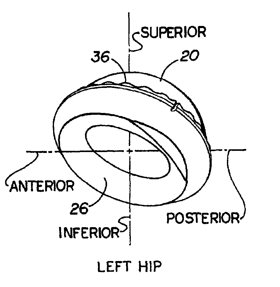
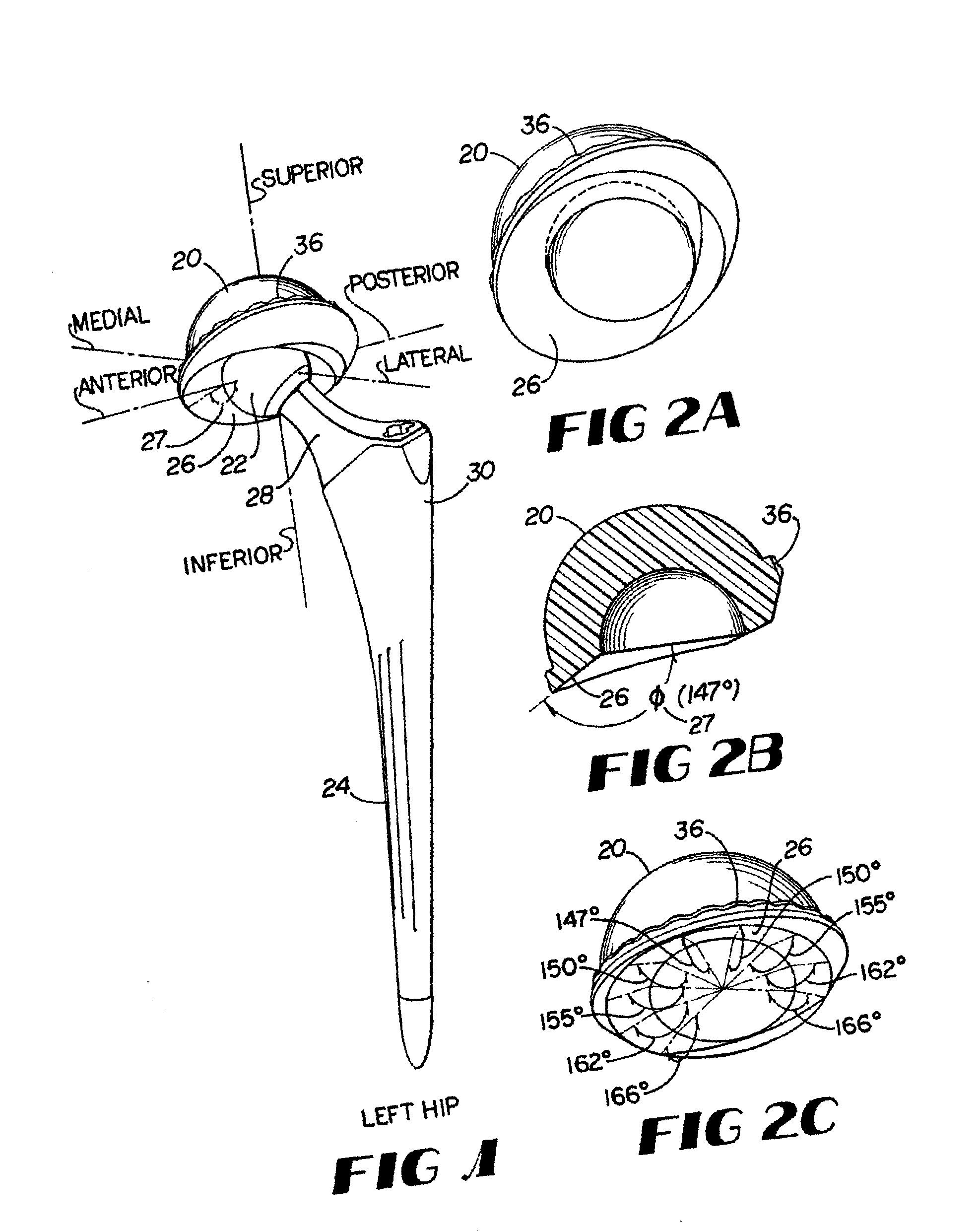
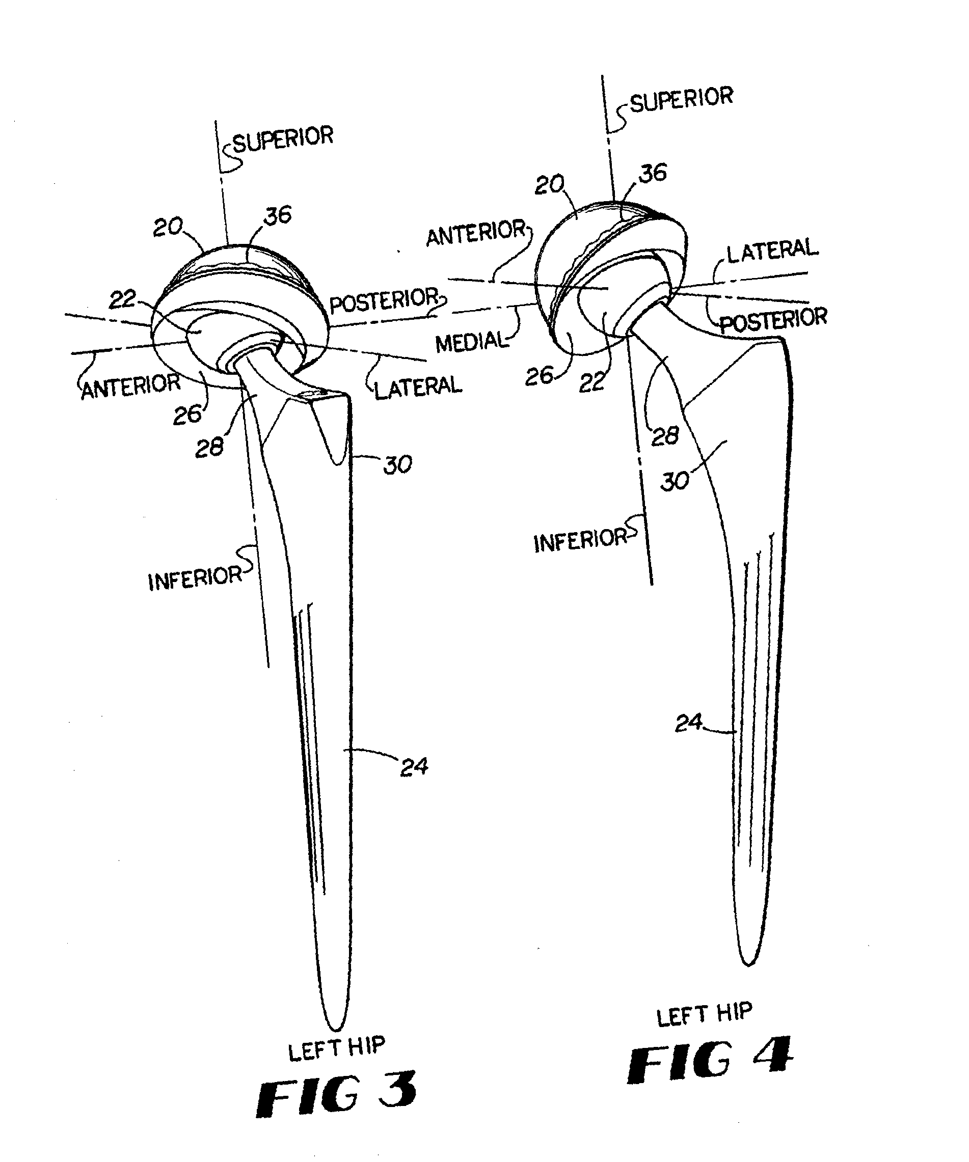
[0018] Methods and structures according to this invention include a method of producing an acetabular liner in which the rim surface geometry varies, rather than being set, in order to optimize the range of motion and minimize interference with the neck of the femoral component. This variable geometry rim surface is employed around the edge of the internal concave surface of the liner, i.e. around the circumference of a generally hemispheric acetabular liner inside diameter, and allows for delayed interference, or impingement, with the neck or stem portion of the femoral component, resulting in an increased range of motion. Thus, this variable geometry rim surface delays when the neck of the femoral component contacts the rim surface of the liner during articulation, allowing an increase in the range of motion of the femoral component and optimization of the liner.
[0019] Increasing the range of motion has many benefits and advantages. For example, increasing the range of motion allows a patient a greater range of movement. Second, an increase in the range of motion provides the surgeon with greater room for error in component positioning, or clocking, during surgery. Since it is not currently possible to accurately measure the precise angle required for implantation of an acetabular component in a particular patient, it is difficult to place an implant at precisely the correct angle. A surgeon generally relies on personal experience in making this assessment. While a locking mechanism, such as a spline interface between the liner and the shell, is beneficial because it allows for multiple reorientations of the liner, fine tuning the positioning of the acetabular component during the intraoperative assessment of range of motion and stability is difficult and often imprecise. Surgeons will benefit from a wider range, or larger target area for acetabular component orientation provided by the increased range of motion.
[0020] Third, a broader range of motion decreases the likelihood of dislocation or subluxation, as it is less likely the femoral component will contact the rim of the liner and lever out of the internal concave surface of the acetabular component. Finally, a broader range of motion aids in preventing wear on the liner or shell. If a femoral component regularly contacts the rim surface of the liner, the liner will wear, releasing polyethylene debris. This debris may cause osteolysis when it escapes into nearby bone and tissue, which may lead to aseptic loosening of the implant. Additionally, if the liner wears thin, the neck of the femoral component may contact the metal shell, resulting in fatigue to the metal that may cause the neck or shell to break, or metal debris to be released into nearby bone and tissue.

Problems solved by technology

Since it is not currently possible to accurately measure the precise angle required for implantation of an acetabular component in a particular patient, it is difficult to place an implant at precisely the correct angle.
While a locking mechanism, such as a spline interface between the liner and the shell, is beneficial because it allows for multiple reorientations of the liner, fine tuning the positioning of the acetabular component during the intraoperative assessment of range of motion and stability is difficult and often imprecise.
Third, a broader range of motion decreases the likelihood of dislocation or subluxation, as it is less likely the femoral component will contact the rim of the liner and lever out of the internal concave surface of the acetabular component.
If a femoral component regularly contacts the rim surface of the liner, the liner will wear, releasing polyethylene debris.
This debris may cause osteolysis when it escapes into nearby bone and tissue, which may lead to aseptic loosening of the implant.
Additionally, if the liner wears thin, the neck of the femoral component may contact the metal shell, resulting in fatigue to the metal that may cause the neck or shell to break, or metal debris to be released into nearby bone and tissue.

Method used


Image

  • Variable geometry rim surface acetabular shell liner
  • Variable geometry rim surface acetabular shell liner
  • Variable geometry rim surface acetabular shell liner

Examples


Embodiment Construction

[0041] The following description of the preferred embodiment(s) is merely exemplary in nature and is in no way intended to limit the invention, its application, or uses.

[0042] Methods and structures according to this invention seek to improve the range of motion of the femoral component of a hip prosthesis by varying the rim surface geometry of the rim of an acetabular shell liner in which the femoral component articulates. Varying the geometry of the rim surface relative to the internal concave surface opening or axis of the liner at different areas on the liner allows for optimization of the rim surface geometry, thus providing an increased range of motion. A variable geometry rim surface liner according to this invention has an overall range of motion generally at least comparable to a conventional constant geometry rim surface liner.

[0043] Optimization of the acetabular shell liner rim surface geometry requires consideration of many elements in the design of the liner, includi...


PUM


Abstract

An acetabular shell liner having a variable rim surface geometry, which improves range of motion of the femoral component within the liner and decreases the incidence of dislocation and subluxation, and methods of making and using the acetabular shell liner. Prosthetic devices, more particularly hip joint prostheses, containing the acetabular shell liner having a variable rim surface geometry are also provided.

Description

CROSS-REFERENCE TO RELATED APPLICATIONS [0001] This application is a continuation of U.S. patent application Ser. No. 09 / 808,228 filed on Mar. 14, 2001, which claims priority to U.S. Provisional Patent Application No. 60 / 189,182 filed on Mar. 14, 2000. The disclosure of this prior application is incorporated by reference in its entirety.BACKGROUND OF THE INVENTION [0002] 1. Field of The Invention [0003] This invention relates generally to acetabular prosthetic devices and more particularly to an improved acetabular shell liner wherein the liner has a variable geometry rim surface. [0004] 2. Related Art [0005] Artificial implants, including hip joints, shoulder joints and knee joints, are widely used in orthopedic surgery. Hip joint prostheses are common. The human hip joint acts mechanically as a ball and socket joint, wherein the ball-shaped head of the femur is positioned within the socket-shaped acetabulum of the pelvis. In a total hip joint replacement, both the femoral head and...

Claims


Application Information

Patent Timeline
Patent Type & Authority Applications(United States)
IPC IPC(8): A61F2/34A61B17/86A61F2/00A61F2/30A61F2/32A61F2/36A61F2/46
CPCA61B17/86A61F2/3094A61F2/30942A61F2/32A61F2/34A61F2/36A61F2310/00179A61F2002/3443A61F2002/349A61F2002/3611A61F2002/4631A61F2310/00011A61F2002/30952
Inventor MCKINNON, BRIAN
Owner SMITH & NEPHEW INC
Why Eureka
Try Eureka