Unlock instant, AI-driven research and patent intelligence for your innovation.

Communication apparatus and its control method

a communication apparatus and control method technology, applied in the field of network communication assistance for information processing apparatuses, can solve problems such as the disconnection of wireless communication, and achieve the effect of quick restoration of information processing apparatuses in networks

Inactive Publication Date: 2006-10-26
CANON KK
View PDF67 Cites 39 Cited by
  • Summary
  • Abstract
  • Description
  • Claims
  • Application Information

AI Technical Summary

Benefits of technology

[0008] According to the present invention, restoration of an information processing apparatus in a network can be performed quickly.

Problems solved by technology

However, wireless communication may be disconnected due to the surrounding environment or the like, unlike wire communication.
A higher level information transfer protocol for implementing wireless direct printing does not define a solution for a wireless-specific error such as disconnection of a wireless channel.
However, a timer for monitoring detection of a “data delay” is set to time out after a relatively long time (e.g., 2 minutes).

Method used


Image

  • Communication apparatus and its control method
  • Communication apparatus and its control method
  • Communication apparatus and its control method

Examples


first embodiment

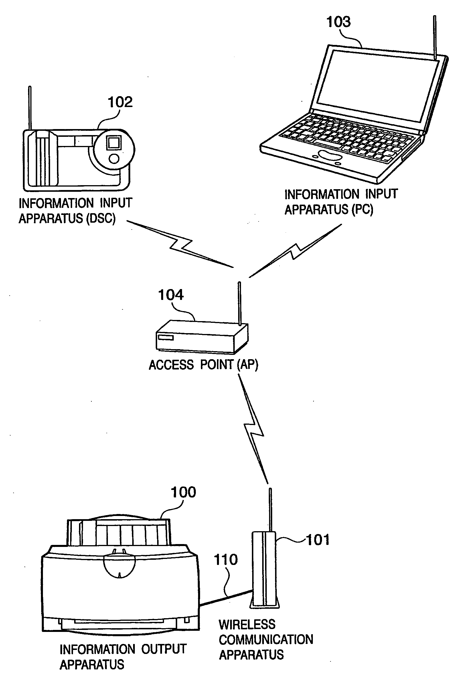
[0019]FIG. 1 is a view showing an example of a wireless communication system according to an embodiment. This embodiment will be explained using an information output apparatus (an image output apparatus such as a printer, copying machine, or multifunction machine, a display apparatus, or the like) 100 as an example of an external apparatus. The information output apparatus 100 is connected to a wireless communication apparatus 101 by a USB (Universal Serial Bus) cable or the like.

[0020] The wireless communication apparatus 101 performs communication based on IEEE802.11x typified by IEEE802.11a / b / g or the like. With this wireless communication, the wireless communication apparatus 101 connects with a first information input apparatus 102 (e.g., a digital camera (DSC) or the like) and a second information input apparatus (e.g., a personal computer (PC) or the like) 103 at least over a wireless network. In the example of FIG. 1, an infrastructure network in which an access point 104 ...

second embodiment

[0068]FIG. 6 is an exemplary sequence chart of another wireless communication sequence according to an embodiment. Note that an explanation of parts which are the same as or similar to those in the above-described sequence will be simplified by denoting them with the same reference numerals.

[0069] For example, we assume that when an information output apparatus 100 and an information input apparatus 103 are communicating with each other at least partly over a wireless network (S301), the wireless network is disconnected (S306, S307, and S308). At this time, a wireless communication apparatus 101 multicasts a network drop-out notification (S601, S602, and S603). With this operation, the information output apparatus 100 is considered not to exist on the wireless network. Examples of a network drop-out notification include a Bye-Bye signal serving as a disconnection request message in UPnP (Universal Plug and Play). After that, the wireless communication apparatus 101 simulatedly disc...


PUM


Abstract

A wireless communication apparatus recognizes whether an information input apparatus is in a wirelessly communicable state at periods shorter than a disconnection waiting time in an information transfer protocol which transfers information between the information input apparatus and an information output apparatus. If the wireless communication apparatus recognizes that the information input apparatus is not in the wireless communicable state, it permits and expedites processing of a request for connection with the information output apparatus sent from another information input apparatus over a wireless network.

Description

FIELD OF THE INVENTION [0001] The present invention relates to a technique for aiding an information processing apparatus in network communication. BACKGROUND OF THE INVENTION [0002] To output information (image data or the like) input in an information input apparatus (digital camera or the like) from an information output apparatus (printer or the like), it has conventionally been necessary to temporarily store the image data in a personal computer (PC). [0003] In recent years, digital camera users who do not possess PCs have been increasing. Also users who want to print images stored in a digital camera more easily have been increasing. Under the circumstances, to meet the needs of such users, a “direct print” method has been proposed, i.e., a method of directly connecting a digital camera and a printer by a cable to perform printing (Japanese Patent Laid-Open No. 11-239312). [0004] If a wireless network replaces a connection cable in a direct print method described above, users ...

Claims


Application Information

Patent Timeline
IPC IPC(8): G06F15/16H04W76/02
CPCH04N1/00278H04N2101/00H04L67/02H04W76/02H04N2201/0055H04W76/10H04L12/40032H04L12/40123
Inventor HIROSE, TAKATOSHINAGO, HIDETADAFUJII, KENICHISHICHINO, TAKAHIRO
Owner CANON KK