
Liftable turfing systems

a turfing system and lift technology, applied in water skiing, sports equipment, ski bindings, etc., can solve the problems of large turf segments that are difficult to lift and transport, turf is placed under great stress, and does not get the best exposure to sun and moisture, etc., to achieve convenient location

Inactive Publication Date: 2006-11-02
STRATHAYR
View PDF14 Cites 53 Cited by
  • Summary
  • Abstract
  • Description
  • Claims
  • Application Information

AI Technical Summary

Benefits of technology

[0005] However, large turf segments are difficult to lift and transport without damaging the turf segment or surrounding turf areas. Whilst forklifts have proved very successful in facilitating loading and unloading of turf segments there is often no ready access for forklift tines when damaged or worn turf segments have to be removed and replaced.
[0020] In a preferred embodiment each corner of the pallet is located on a locator plate that facilitates the location of one corner of four adjacent pallets.

Problems solved by technology

If natural turf is required to play team sports and the stadium is used for other entertainment purposes such as to house concerts, the turf is placed under great stress.
In consequence, the turf does not get optimum exposure to sun and moisture to ensure healthy grass growth.
However, large turf segments are difficult to lift and transport without damaging the turf segment or surrounding turf areas.
Whilst forklifts have proved very successful in facilitating loading and unloading of turf segments there is often no ready access for forklift tines when damaged or worn turf segments have to be removed and replaced.
Although early versions of synthetic / artificial turf could be easily rolled up and removed, later versions that are a rubber / sand infill cannot be rolled up.

Method used


Image

  • Liftable turfing systems
  • Liftable turfing systems
  • Liftable turfing systems

Examples


Embodiment Construction

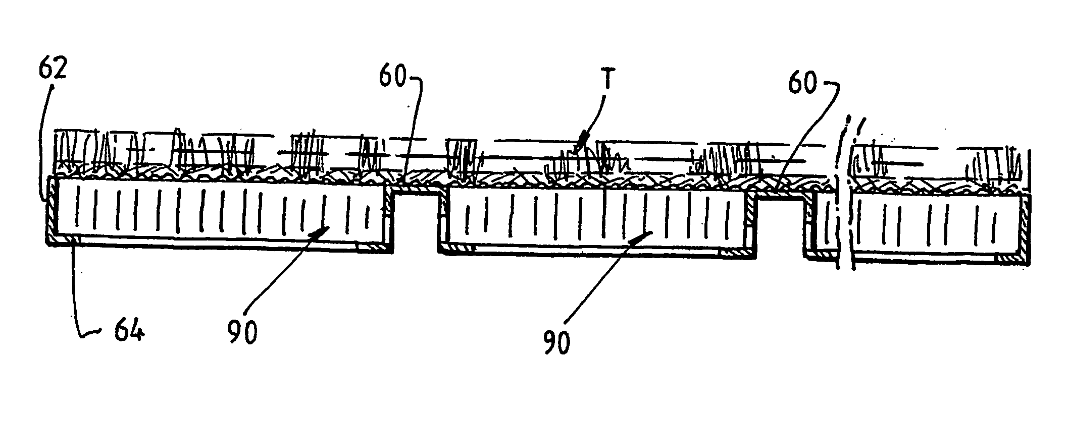
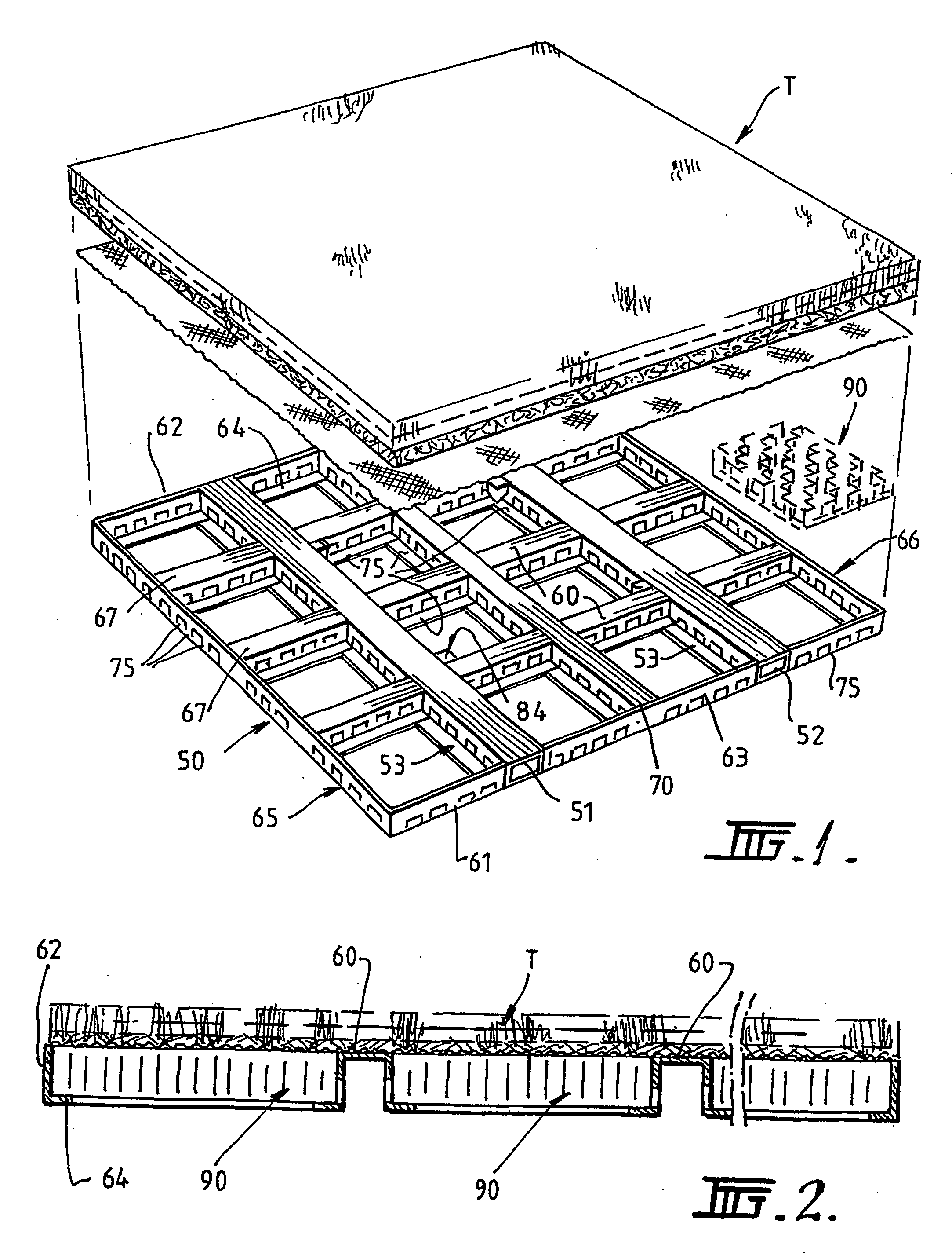
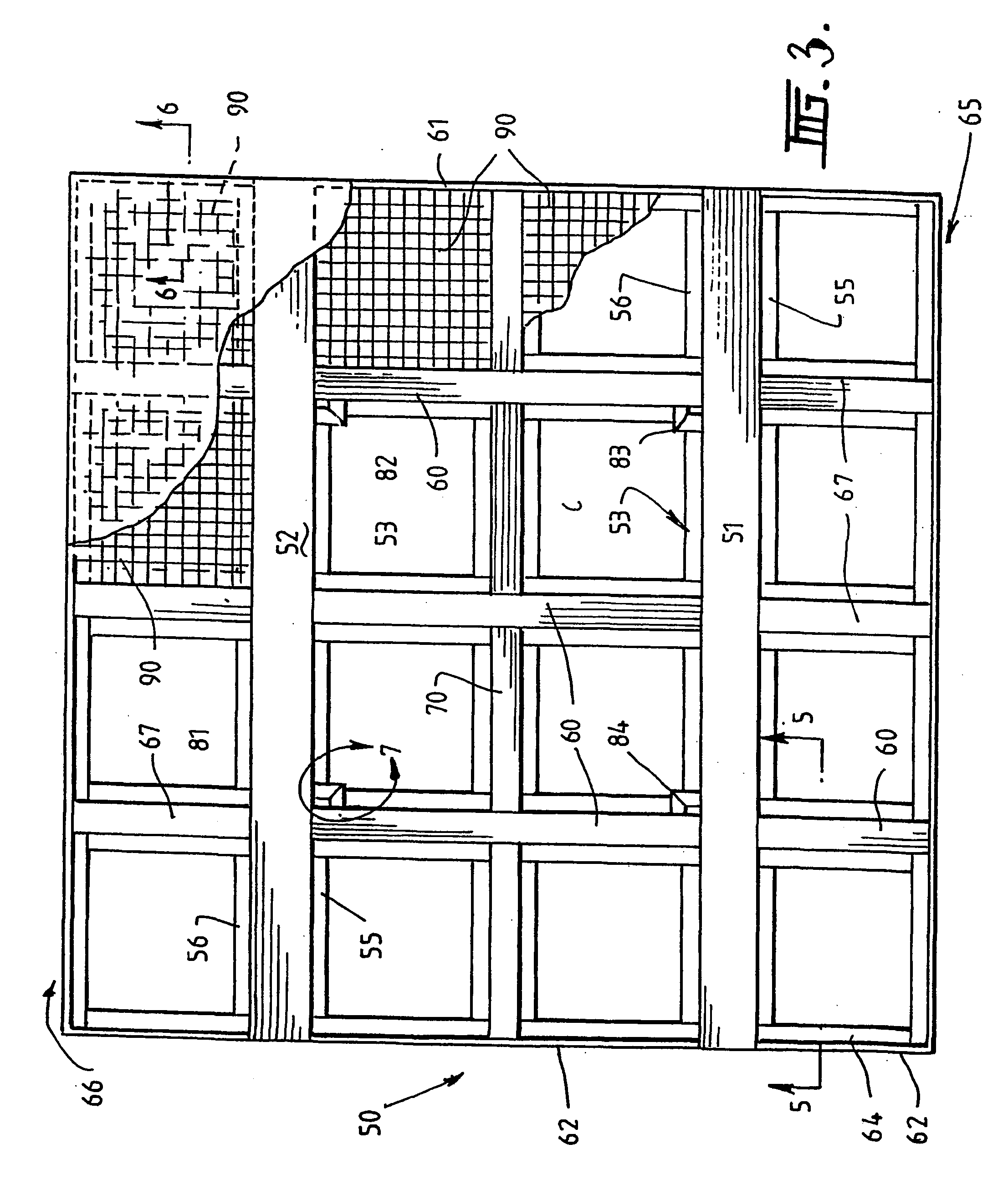
[0056] In a first embodiment as shown in FIG. 1-8 of the accompanying drawings a turf module 10 comprises natural turf T positioned on a support structure in the form of a metal skeletal framework 50 that supports a plastics latticework 90 with the turf T covering the upper surface.

[0057] The framework 50 is fabricated to be either a square (preferably 2.4 m) or a rectangle in plan (5 m×3 m) with subsections that are arranged to support the plastics latticework 90 that sits in each subsection. The frame 50 is fabricated from steel and essentially comprises two parallel spaced apart main beams 51, 52 of a inverted C-shape. A plate 53 is welded to the underside of the beams to extend outwardly on each side of the beam to define a small ledge 55, 56 that will run along on the underside of each edge of the beam. The main beams 52, 53 are spaced by lateral spacing beams 60 that are formed, as shown in FIG. 5, to have a top hat shape in section. These beams 60 are equally spaced between ...


PUM


Abstract

A liftable support structure for a turf system, the support structure comprising a skeletal framework having an open based structure with upstanding sides and at least two parallel spaced cross beams, the framework defining open subsections, each subsection having a base defining a ledge structure, each subsection supporting a latticework panel that sits on the ledge structure, the framework having a plurality of spaced lifting points and the cross beams defining access to forklift tines. A pallet for natural or artificial turf comprising a structure moulded in foamed plastics to have a closed planar top surface supported by a lattice work of mutually perpendicular walls defining a flexible open base, the structure defining a pair of elongate spaced parallel channels extending across each side to facilitate forklift tine entry.

Description

CROSS-REFERENCE TO RELATED APPLICATIONS [0001] The present application is a continuation-in-part application of U.S. application Ser. No. 10 / 475,613, filed May 4, 2004, now pending[0002] This invention relates to turfing systems and especially liftable turfing systems that can be used in modern stadia and are readily movable from an operative position to a storage growing environment. [0003] Modern day stadia place enormous demands on turfing areas. If natural turf is required to play team sports and the stadium is used for other entertainment purposes such as to house concerts, the turf is placed under great stress. Modern day stadia also have cantilevered overhanging stands that place much of the turf in shade and some stadia even have closeable roof structures. In consequence, the turf does not get optimum exposure to sun and moisture to ensure healthy grass growth. [0004] There have been many proposals to provide removable turf segments that can be removed and interchanged on de...

Claims


Application Information

Patent Timeline
IPC IPC(8): A01G9/02A01G1/00A63C19/00E01C13/00E01C13/08
CPCA63C19/00A01G1/007E01C2013/006E01C13/083A01G9/033
Inventor CASIMATY, GABRIELCASIMATY, FRANK GREGORYMCCULLAGH, JOSEPH JOHNAISENBERG, YORAM
Owner STRATHAYR
Learn More