Ice maker with adaptive fill

Inactive Publication Date: 2006-11-02
NIDEC MOTOR CORP
View PDF37 Cites 63 Cited by
  • Summary
  • Abstract
  • Description
  • Claims
  • Application Information

AI Technical Summary

Benefits of technology

[0009] According to a second aspect of the disclosure, a method of producing ice, comprises the steps of performing successive ice making cycles, determining if a size characteristic of said ice member produced during a first ice making cycle is less than a threshold value and generating a control signal in response thereto and increasing a magnitude of said water advancement period for a subsequent ice making cycle in re

Problems solved by technology

Unfortunately, timers alone cannot guaranty consistent fill levels.
Over time, water lines tend to become corroded or

Method used


Image

  • Ice maker with adaptive fill
  • Ice maker with adaptive fill
  • Ice maker with adaptive fill

Examples


first embodiment

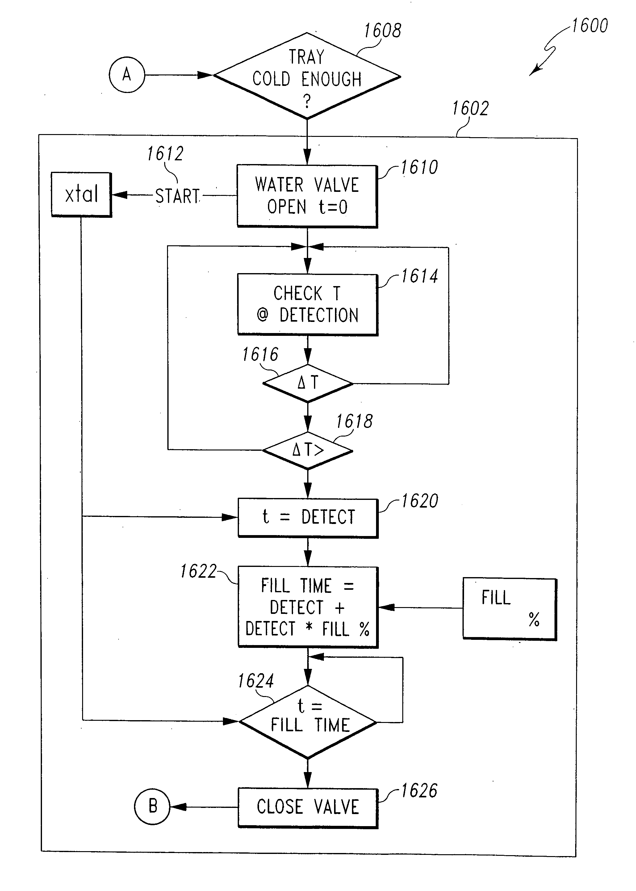
[0065] Initially, in the disclosure (as described more fully below), the fill time is based on the required time to fill the ice tray 20 to a particular location at which a known portion of the entire volume of the tray 20 has been filled and continued for a time proportional to the remaining volume of the tray 20 and the time required to fill to the particular location. In an alternative embodiment of the disclosure, the level of the water in the last compartment 66f to be filled may be sensed. In yet another embodiment of the disclosure, the water filling operation is based on a set time that is calibrated to estimate proper filling of all of the compartments 66 of the tray 20. In each of the embodiments, the total time that the water solenoid valve 32 is open is adjusted in either the current or subsequent filling cycles based on a determination of a fill level error.

[0066] Cessation of the filling operation may be accomplished in various ways, however, the illustrated icemaker a...

second embodiment

[0107] In the disclosed second embodiment of adaptively filling an ice tray 2200, the level to which the ice tray 20 has been filled is detected by displacing water with the ejector members 52 until the water rises to a level where it is detected by an overfill sensor 117 in the overflow trough 114, as shown for example, in FIGS. 22 and 23. In the illustrated embodiment, the overflow trough 114 is formed in the first end wall 76 of the front compartment 66f of the ice tray 20. Water flows into the overflow trough 114 when each compartment 66 is filled to the desired level and the ejector members 52 are in a desired position to displace water in the compartments 66. The overflow sensor 117 may be a conductor pin insulated from the tray 20 and positioned to sense presence of water in the overflow trough 114.

[0108] In the second embodiment of the disclosed ice maker assembly 10 the stepper motor 42 is utilized to precisely fill the compartments 66 of the ice tray 20. Because a stepper ...


PUM


Abstract

An icemaker assembly includes an ice tray having an ice forming compartment, a water line configured to advance water from a water source to the ice tray, a valve operable to selectively block advancement of water through the water line while an actuation signal is generated, a control system operable to generate the actuation signal for a water advancement period, a water level detection system for determining if a level of water in the ice forming compartment is below a threshold value and generating a control signal in response thereto. The control system is further operable to alter a magnitude of the water advancement period in response to generation of the control signal. Water is initially advanced into the ice forming compartment for a first period of time during a first ice making cycle by opening the valve. If it is determined that the level of water in the ice forming compartment is below a threshold value during the first ice making cycle, a control signal is generated in response thereto and during a second ice making period the valve is opened for a second period of time in response to generation of the control signal so that water advances into the ice forming compartment of said ice tray through the valve during said second ice making cycle for a period of time that is greater than the first period of time.

Description

CROSS REFERENCE [0001] Cross reference is made to co-pending U.S. patent application Ser. No. 10 / 895,665 (Attorney Docket No. 1007-0574) filed Jul. 21, 2004, entitled Method and Device for Stirring Water During Icemaking, U.S. patent application Ser. No. 10 / 895,792 (Attorney Docket No. 1007-0577) filed Jul. 21, 2004, entitled Method and Device for Eliminating Connecting Webs Between Ice Cubes and U.S. patent application Ser. No. 10 / 895,570 (Attorney Docket No. 1007-0579) filed Jul. 21, 2004, entitled Method and Device for Producing Ice Having a Harvest-facilitating Shape, which are assigned to the same assignee as the present invention, the disclosures of which are hereby incorporated by reference in their entirety.BACKGROUND AND SUMMARY [0002] This invention relates to icemakers for household refrigerators and more particularly to ice makers that adjust the fill time based upon a sensed level of filling of the ice tray. [0003] Conventional ice makers typically provide an ice tray i...

Claims


Application Information

Patent Timeline
IPC IPC(8): F25C1/00
CPCF25C1/04F25C5/08F25C2700/04F25C2400/14F25C2600/04F25C2400/10F25C2305/024
Inventor COLE, RONALD E.SLOCUM, LAURENCE S.TREMBLAY, DENNISTREMBLAY, YOUNG
Owner NIDEC MOTOR CORP
Why Eureka
Try Eureka