Condenser with integral receiver and capable of upflow operation

Active Publication Date: 2006-11-02
MAHLE INT GMBH
View PDF5 Cites 7 Cited by
  • Summary
  • Abstract
  • Description
  • Claims
  • Application Information

AI Technical Summary

Benefits of technology

[0010] The subject invention overcomes the limitations of the art by providing a condenser with an integrally formed receiver that utilizes a conduit which is completely enclosed within the interior of the receiver. Disposing the entire conduit inside the recei

Problems solved by technology

However, extending the communications pipe through the receiver cover and attaching the upper portion directly to the return tank increases the number of exterio

Method used


Image

  • Condenser with integral receiver and capable of upflow operation
  • Condenser with integral receiver and capable of upflow operation
  • Condenser with integral receiver and capable of upflow operation

Examples


Example

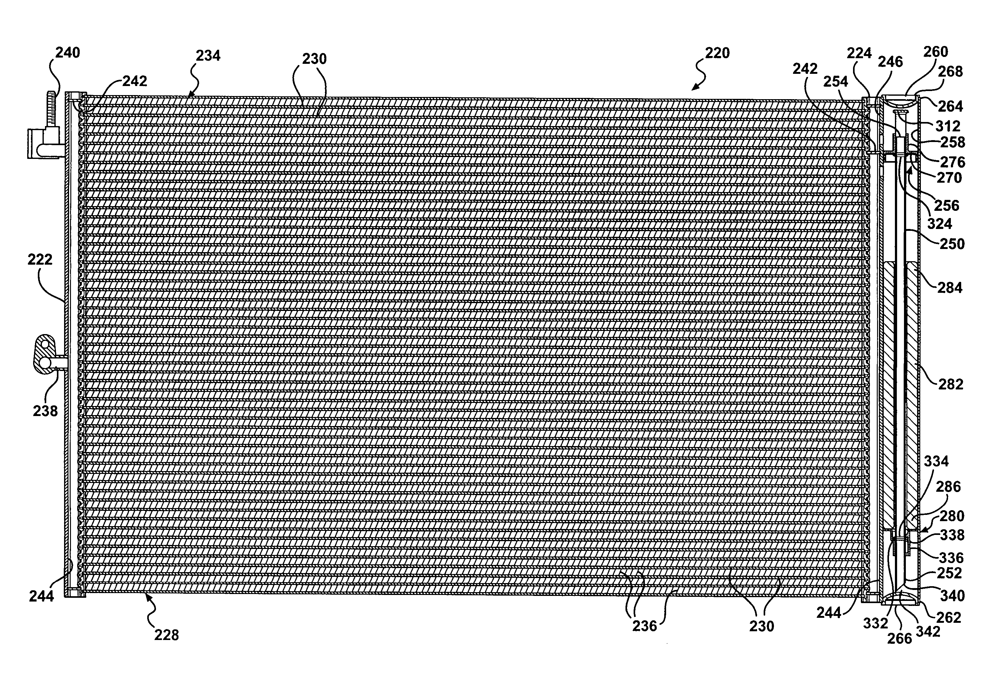
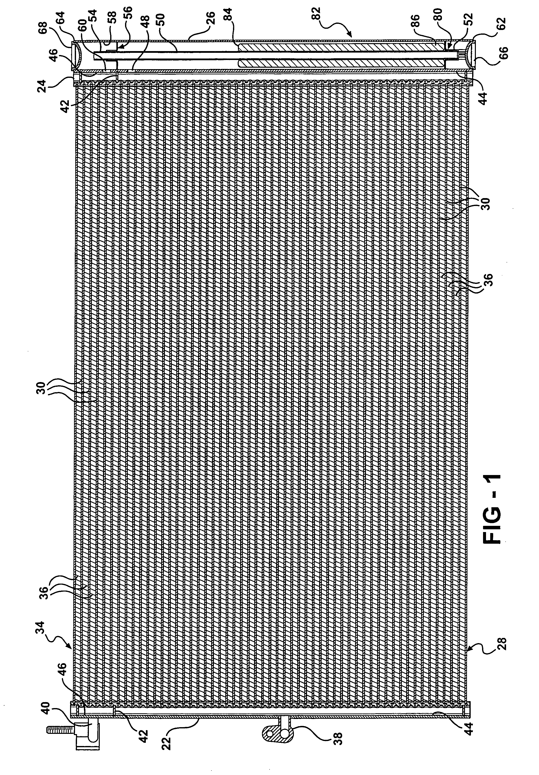
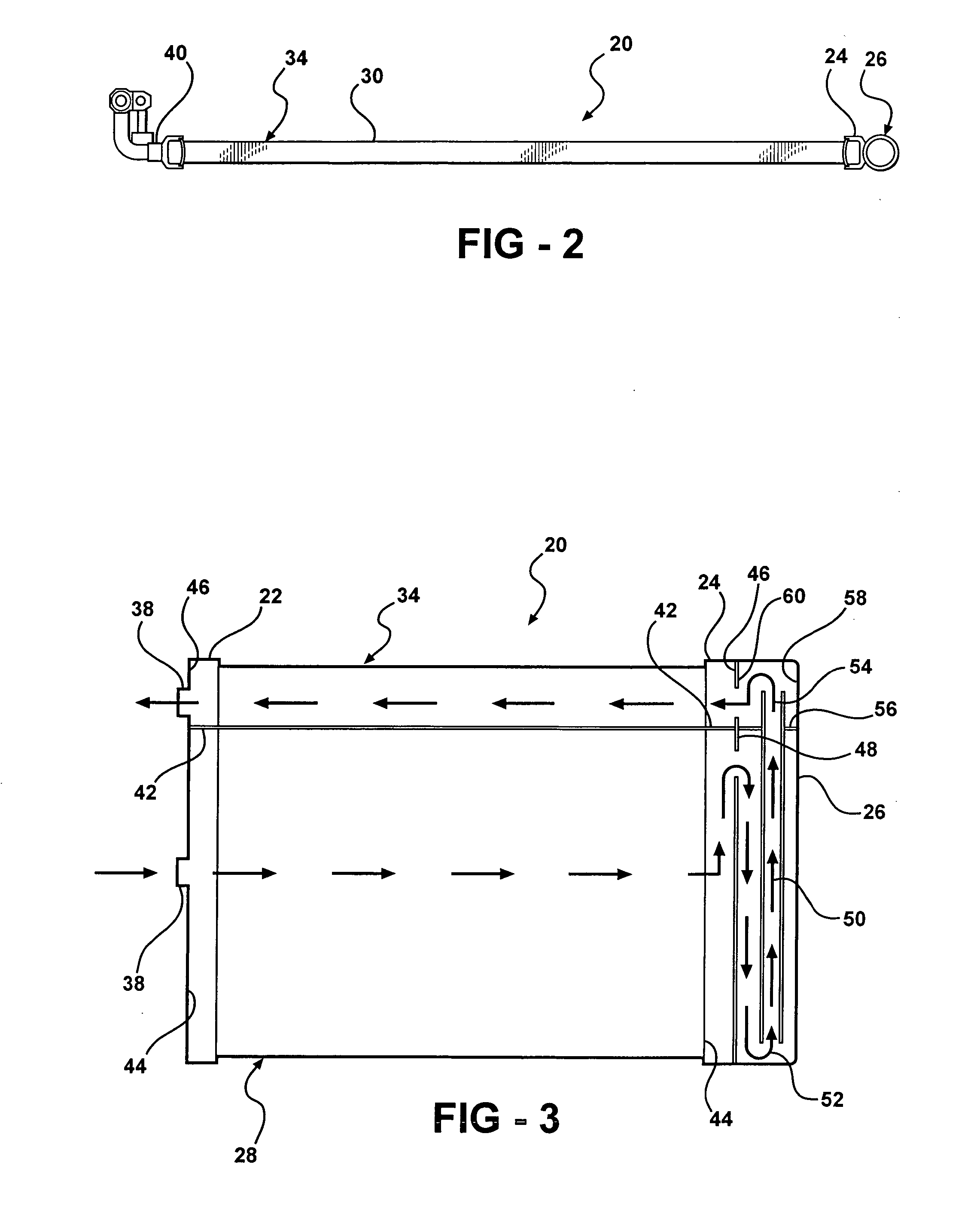
[0028] Referring now to the Figures, wherein like numerals indicate like or corresponding parts throughout the several views, a condenser for an air conditioning system is generally shown at 20 in FIGS. 1 through 3. The condenser 20 includes a first header 22, a second header 24, and a receiver 26. The receiver 26 extends parallel to the second header 24.

[0029] As is best shown in FIG. 3, a first group 28 of tubes 30 extends between the first and second headers 22, 24. The tubes 30 in the first group 28 are in fluid communication with the headers 22, 24, which permits a fluid 32 to flow between the headers 22, 24 and through the first group 28. A second group 34 of tubes 30 also extends between the first and second headers 22, 24. Like the tubes 30 in the first group 28, the tubes 30 in the second group 34 are in fluid communication with the headers 22, 24, which similarly permits the fluid 32 to flow between the headers 22, 24 through the second group 34. As is shown in FIG. 1, a ...


PUM


Abstract

A condenser for an air conditioning system includes a receiver integrally formed with a second, or return, header which is in fluid communication with a second, or sub-cooling, group of tubes. A conduit extends between entry and discharge ends both of which are completely enclosed within the interior of the receiver. The conduit transports a refrigerant fluid in an upflow direction within the interior of the receiver and through a second fluid port located adjacent the discharge end of the conduit for directing the fluid into and through the return header to the sub-cooling group of tubes.

Description

BACKGROUND OF THE INVENTION [0001] 1. Field of the Invention [0002] This invention relates to air conditioning systems. More specifically, the invention relates to an integral receiver assembly for a sub-cooled condenser. [0003] 2. Description of the Related Art [0004] Condensers designed for upflow operation and which utilize integral receivers are well known in the art. Such condensers often utilize receivers which are connected to, or otherwise integrally formed with, the return header of the condenser. An example of such a condenser is disclosed in U.S. Pat. No. 6,3,97,627 (“Aki et al.”). The Aki et al. condenser includes a plurality of tubes through which a refrigerant fluid flows between initial and return header tanks. The tubes are divided into an upstream group within which the fluid is condensed from a gas to a liquid, and a downstream, or “sub-cooling” group within which the condensed fluid is further cooled prior to exiting the condenser. The sub-cooling group is dispose...

Claims


Application Information

Patent Timeline
IPC IPC(8): F25B39/04
CPCF25B39/04F25B2339/0441F25B40/02
Inventor KENT, SCOTT EDWARDSCHERER, LAWRENCE P.SOUTHWICK, DAVID A.
Owner MAHLE INT GMBH
Why Eureka
Try Eureka