Method for cleaning a stationary gas turbine unit during operation

a gas turbine unit and cleaning technology, applied in the direction of cleaning process and apparatus, electrostatic cleaning, hollow article cleaning, etc., can solve the problems of gas turbines consuming large quantities of air, deteriorating aerodynamic properties, and pressure step-up losses, so as to increase the roughness of the surface, and reduce the effect of pressure step-up losses

Inactive Publication Date: 2006-11-02
GAS TURBINE EFFICIENCY
View PDF8 Cites 41 Cited by
  • Summary
  • Abstract
  • Description
  • Claims
  • Application Information

AI Technical Summary

Benefits of technology

[0004] Gas turbines consume large quantities of air. Air contains particles in the form of aerosols which are drawn into the compressor of the gas turbine with the air flow. A majority of these particles accompany the air flow and leave the gas turbine with the exhaust gases. However, some particles tend to adhere to components in the channels of the gas turbine. These particles form a deposit on the components, thus deteriorating the aerodynamic properties. As with increased roughness of the surface, the coating causes a change in the boundary layer flow along the surface. The coating, i.e. the in

Problems solved by technology

Gas turbines consume large quantities of air.
However, some particles tend to adhere to components in the channels of the gas turbine.
These particles form a deposit on the components, thus deteriorating the aerodynamic properties.
The coating, i.e. the increased roughness of the surface, results in pressure step-up losses and a reduction in the amount of air the compressor compresses.
For the compressor as a whole this entails deteriorated efficiency, reduced mass flow and reduced final pressure.
The drawback is that the nut-shell material may find its way into the internal air system of the gas turbine and result in clogging of ducts and valves.
The method results in the compressor components being drenched in cleaning fluid and the dirt particles being det

Method used


Image

  • Method for cleaning a stationary gas turbine unit during operation
  • Method for cleaning a stationary gas turbine unit during operation
  • Method for cleaning a stationary gas turbine unit during operation

Examples


Embodiment Construction

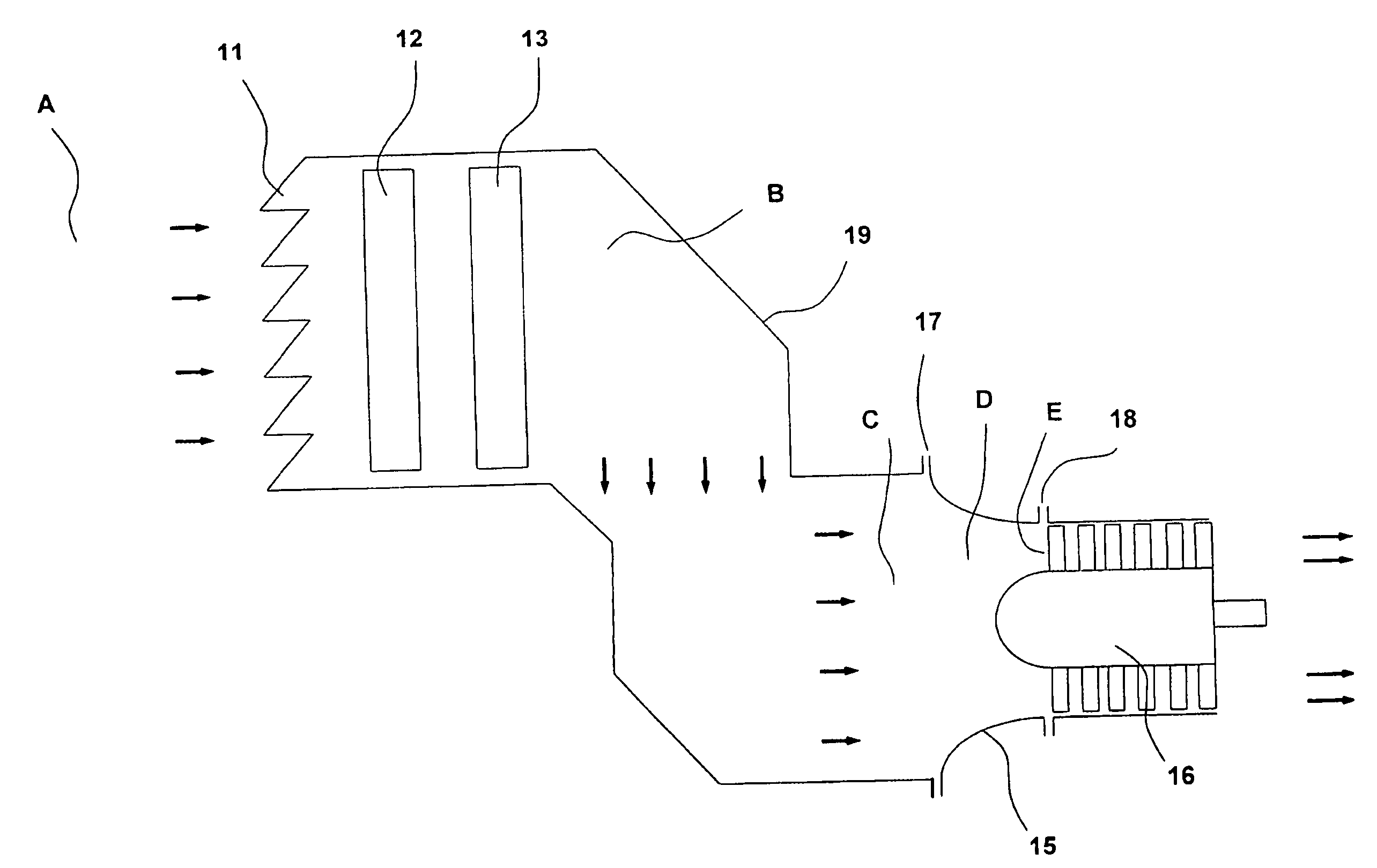
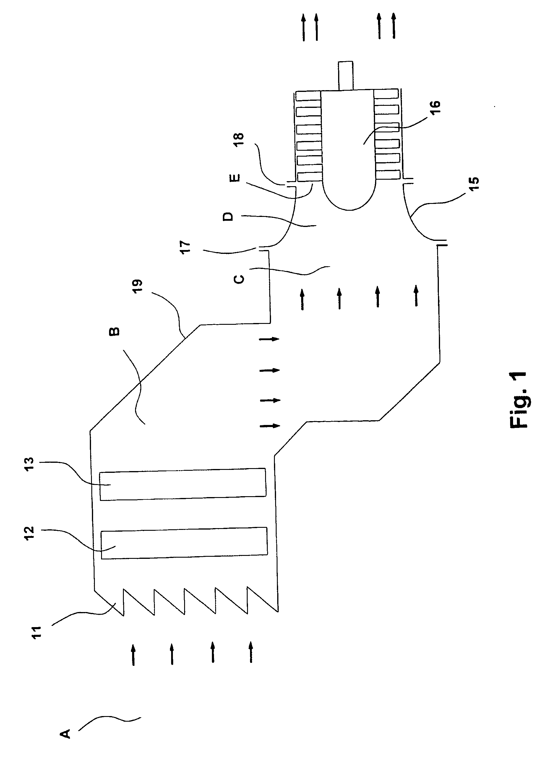
[0019] Air drawn into the compressor is accelerated to high speeds in the air duct prior to compression. FIG. 1 shows the design of an air duct for a gas turbine. The direction of flow is indicated by arrows. The surrounding air A is assumed to have no initial velocity. After having passed weather protection 11, filter 12 and dirt trap 13 the air velocity at B is 10 m / s. The air velocity increases further at C to 40 m / s as a result of the decreasing cross sectional area of the air duct. Immediately prior to the first blade E of the compressor the air passes a duct especially designed to accelerate the air to extremely high speeds. Between its inlet C and its outlet E the acceleration duct 15 is called the “bell mouth”15. The purpose of the bell mouth is to accelerate the air to the speed required for the compressor to perform its compression work. The bell mouth 15 is connected to the duct 19 by the joint 17. The bell mouth 15 is connected to the compressor 16 by the joint 18.

[0020...


PUM


Abstract

A method for cleaning a stationary gas turbine unit during operation, wherein the unit comprises a turbine, a compressor driven by the turbine, the compressor having an inlet, an air inlet duct arranged upstream of the air inlet of the compressor, the inlet duct having a part of the duct adjoining the inlet of the compressor and having decreasing cross section in the flow direction in order to give the air flow a final velocity at the inlet to the compressor. A spray of cleaning fluid is introduced in the inlet duct. The cleaning fluid is forced through a spray nozzle with a pressure drop exceeding 120 bar to form a spray the drops of which have a mean size that is less than 150 μm. The spray is directed substantially parallel to and in the same direction as the direction of the air flow. The spray is introduced at a position in the duct section where the air velocity is at least 40 percent of the final velocity at the compressor inlet, so that the drops of the liquid spray are caused to acquire a slip ratio of at least 0.8 at the compressor inlet.

Description

[0001] The invention relates to a method for cleaning a stationary gas turbine unit during operation, of the type revealed in the preamble to claim 1. [0002] The invention thus relates to washing gas turbines equipped with axial or radial compressors. Gas turbines comprise a compressor for compressing air, a combustion chamber for burning fuel together with the compressed air, and a turbine to drive the compressor. The compressor comprises one or a plurality of compression steps, each compression step consisting of a rotor disc having blades and a following stator disc with guide vanes. [0003] One object of the invention is to provide a method for cleaning blades and vanes from deposits of foreign substances by injecting fluid drops into the air flow upstream of the compressor. The fluid drops are transported with the air flow into the compressor where they collide with the surface of the rotor blades and guide vanes, whereupon the deposits are detached by the chemical and mechanica...

Claims


Application Information

Patent Timeline
IPC IPC(8): B08B9/00F01D25/00
CPCB08B3/02F04D29/705F01D25/002B08B9/00
Inventor ASPLUND, PETERHJERPE, CARL-JOHAN
Owner GAS TURBINE EFFICIENCY
Why Eureka
Try Eureka