Dialysis filter

a technology of dialysis filter and filter body, which is applied in the direction of moving filter element filter, filtration separation, water/sludge/sewage treatment, etc., can solve the problems of affecting the performance of filtration, and achieve the effect of improving the filtering efficiency, low flow resistance, and optimal removal of substances

Inactive Publication Date: 2006-11-02
B BRAUN MEDIZINTECH
View PDF10 Cites 39 Cited by
  • Summary
  • Abstract
  • Description
  • Claims
  • Application Information

AI Technical Summary

Benefits of technology

[0005] According to a first aspect of the invention, an improvement in the filtering efficiency is achieved in that the packing density of the hollow fiber bundle is varied over the length of the bundle and the hollow fiber bundle is widened in particular in the inlet and/or outlet area of the dialysate, while the packing density in the middle portion of the hollow fiber bundle is higher. Hereby a radial flow of the dialysate with as few obstructions as possible is achieved in the widened portion of the bundle, so that a uniform flow distribution over the whole cross section of the bundle results. While the lower packing density leads to low flow resistance in the inlet area and, if applicable, also in the outlet area of the radial flow, in the main part of the filter the higher packing density of the hollow fibers guarantees a uniform flow around the individual hollow fibers in the longitudinal direction. Hereby, optimal substance evacuation is achieved, especially in the inlet and outlet areas, and thus the filtering efficiency is improved.
[0006] According to a second aspect of the invention, in a front-end cap of the tubular casing a disc-shaped flow distributor is provided having on the inflow side an elevation in the area of the inlet pipe, so that homogenous velocity distribution of the blood flowing into the cap results in the radial direction. Hereby, the gap width between the inside wall of the cap and the surface of the flow distributor can be adjusted so that the flow velocity in the inlet area is distributed uniformly. The flow is uniformly widened to the maximum cap diameter. In this way, too, due to optimized guiding of the flow for a...

Problems solved by technology

Several structural shapes of dialysis filters are known, having disadvan...

Method used


Image

  • Dialysis filter
  • Dialysis filter
  • Dialysis filter

Examples


Embodiment Construction

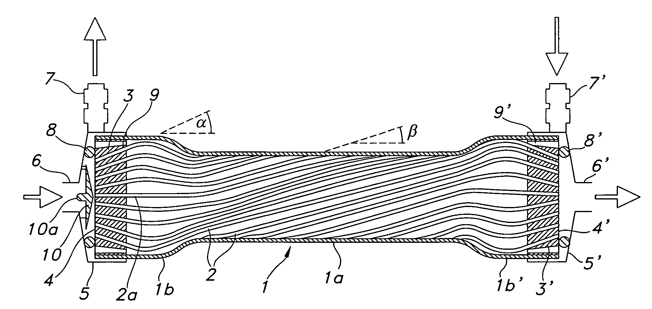
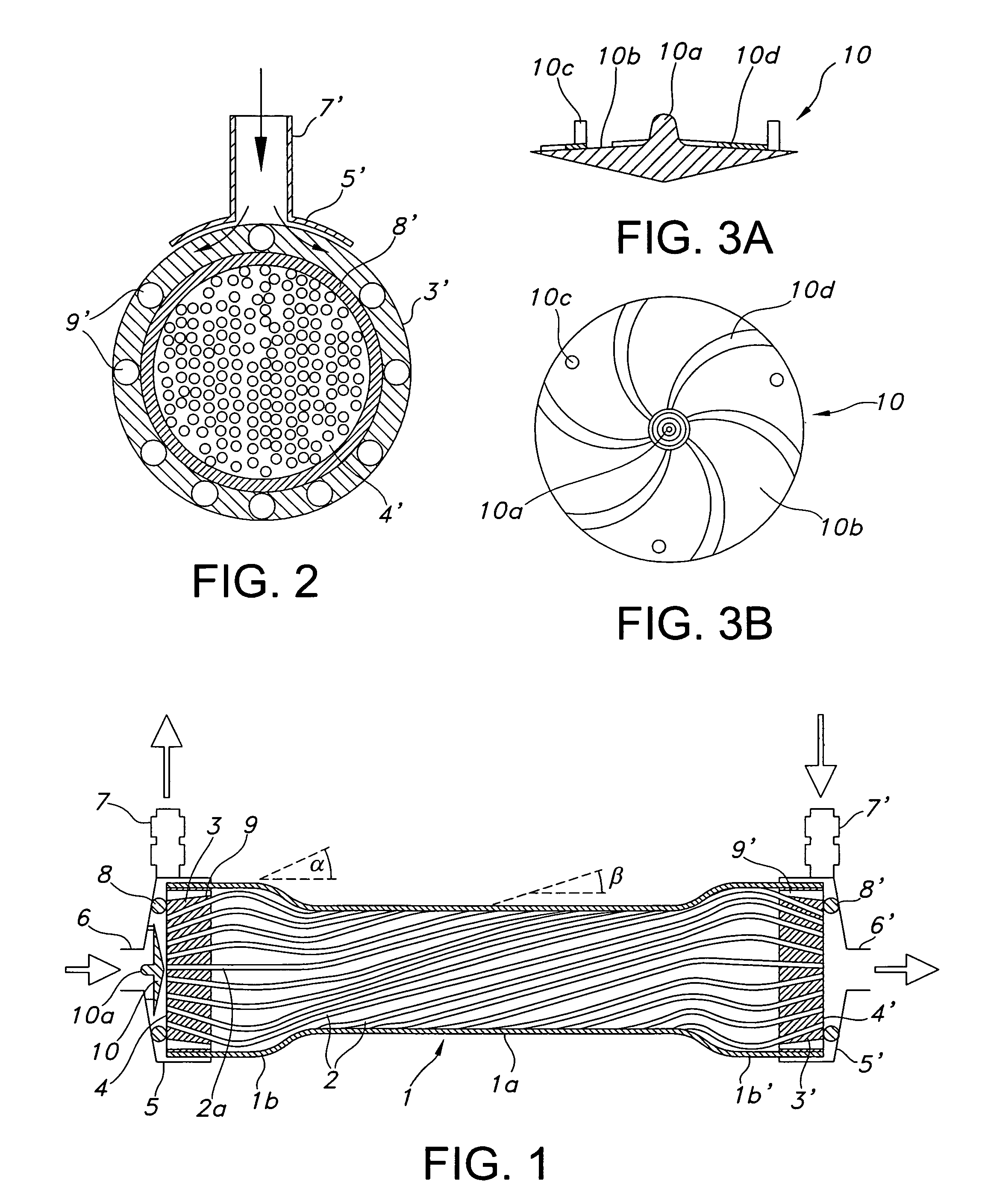
[0016]FIG. 1 shows a longitudinal section through a dialyzer having a generally tubular casing 1, which is closed at the front ends by caps 5 and 5′. In the casing 1 there is a bundle of semi-permeable hollow fibers 2 positioned through two disc-shaped blocks 3 and 3′ of a pottant, the circumference of which abuts on the inner circumference of the tubular casing 1 and in which the ends of the individual hollow fibers 2 of the bundle are liquid-impermeably embedded. The outside of the pottants 3 and 3′ each forms a flat cross section 4 or 4′ of the hollow fibers transverse to the longitudinal axis of the casing having an opening to the inside of the hollow fibers.

[0017] In the embodiment shown in FIG. 1, the section plane 4 is substantially on the level of the edge of the casing 1, wherein the caps 5 extend over the end portion of the casing 1 and are sealed in relation to the casing. However, the section plane 4 can also be arranged offset to the edge of the casing.

[0018] The caps...


PUM

PropertyMeasurementUnit
Lengthaaaaaaaaaa
Flow rateaaaaaaaaaa
Densityaaaaaaaaaa

Abstract

A device for removing substances from blood or other body fluids, comprising a bundle of semi-permeable hollow fibers, the ends of which are embedded and held in a pottant, and a tubular casing surrounding the hollow fiber bundle. At the ends of the casing, inlet and outlet pipes are connected with partitioned fluid chambers formed in the casing. Different aspects are provided to improve the flow properties, for increasing the filtering efficiency, such as varying packing density along the length of the fiber bundle, a distributor disc within a cap, apertures on the circumference of the pottant and an ordered structure of the rippling of the hollow fibers.

Description

[0001] This application claims priority to European Application No. 05008649.5, filed Apr. 20, 2005, which is incorporated in its entirety by reference herein. BACKGROUND OF THE INVENTION [0002] The invention relates to a filter device and more particularly to a dialysis filter. [0003] Several structural shapes of dialysis filters are known, having disadvantages in various respects, each of which impairs performance during filtration. [0004] It is the object of the invention to design a filter device of the type mentioned above such that the filtering efficiency is improved. SUMMARY OF THE INVENTION [0005] According to a first aspect of the invention, an improvement in the filtering efficiency is achieved in that the packing density of the hollow fiber bundle is varied over the length of the bundle and the hollow fiber bundle is widened in particular in the inlet and / or outlet area of the dialysate, while the packing density in the middle portion of the hollow fiber bundle is higher...

Claims


Application Information

Patent Timeline
IPC IPC(8): B01D63/02
CPCA61M1/16B01D61/243B01D63/021B01D63/022B01D63/025B01D2321/2025B01D65/02B01D69/084B01D2313/08B01D2313/10B01D2313/20B01D63/027
Inventor HEINRICH, BERNDMARTINS, KONRADMEHNERT, DIETERMULLER, ECKARDKRACHT, KATRINFRANKE, HORSTHECTOR, RAINER
Owner B BRAUN MEDIZINTECH
Why Eureka
Try Eureka