System and mehod for counting number of layers of multilayer object by means of electromagnetic wave

a multi-layer object and electromagnetic wave technology, applied in the field of systems, can solve the problems of inability to accurately count affecting the performance of the system, etc., and achieve the effect of allowing the accurate counting of the number of layers of a multi-layer obj

Inactive Publication Date: 2006-11-02
CANON KK
View PDF8 Cites 62 Cited by
  • Summary
  • Abstract
  • Description
  • Claims
  • Application Information

AI Technical Summary

Benefits of technology

[0020] Thus, the present invention provides an advantage that the number of layer of an object in a multilayer state can be counted instantaneously by means of a simple arrangement of emitting an electromagnetic wave to strike either the top surface or the bottom surface of the object and a technique of using either reflection or transmission of the electromagnetic wave. The number of layers of a multilayer object can be counted more accurately if both the reflection method and the transmission method are used independently and simultaneously for comparison with each other.

Problems solved by technology

However, the above described known system and method for counting the number of sheets of a multilayer object by projecting light to a lateral surface of the object are accompanied by a problem that the performance of the system is affected by the cut surfaces, if any, of the multilayer object.
For instance, it is not possible to accurately count the number of layers of a multilayer object if the cut surfaces are not uniform because the quantity of transmitted light or that of reflected light changes significantly and irregular reflection occurs there.
Another problem of the above described system and method is that, as the number of layers of the multilayer object increases, the area that needs to be irradiated by the first projector increases so that at least either the first projector or the optical receiver has to be moved in a direction of rectangularly crossing the layers particularly when the number of layers is large.

Method used


Image

  • System and mehod for counting number of layers of multilayer object by means of electromagnetic wave
  • System and mehod for counting number of layers of multilayer object by means of electromagnetic wave
  • System and mehod for counting number of layers of multilayer object by means of electromagnetic wave

Examples


embodiment 1

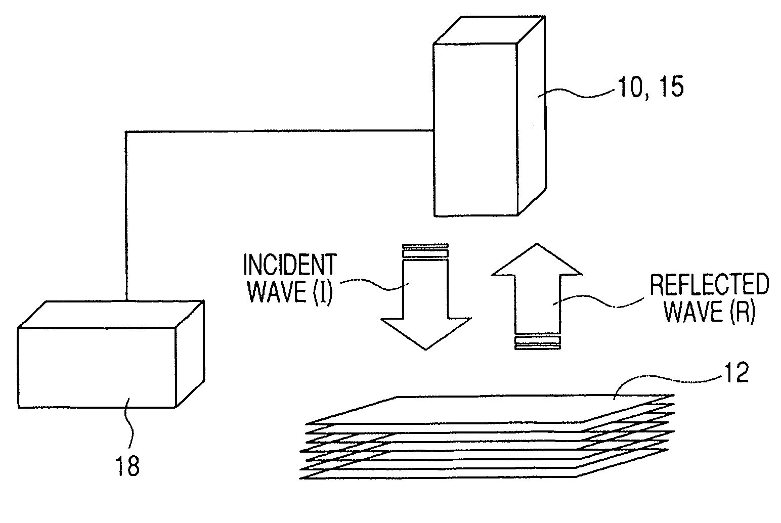
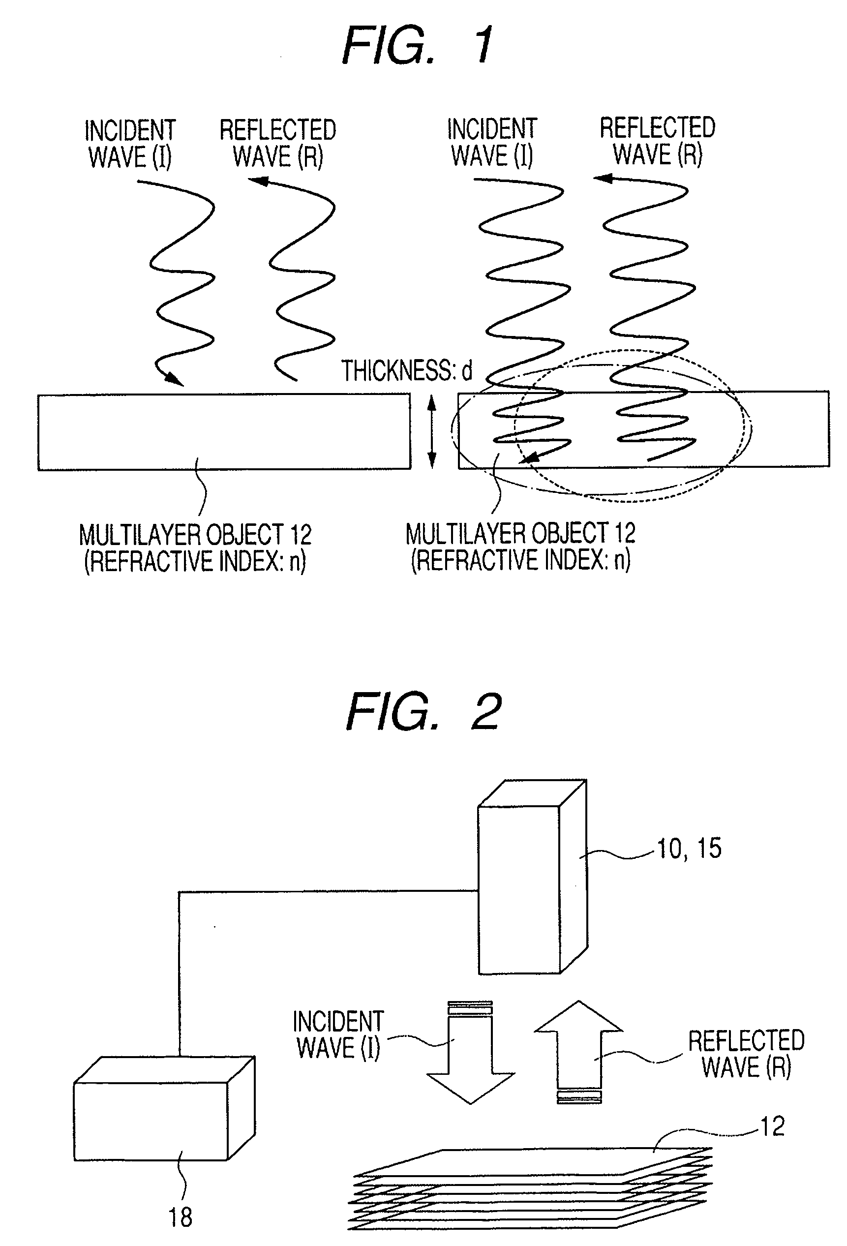
[0034]FIG. 2 is a schematic illustration of the first embodiment of system for counting the number of layers of a multilayer object according to the invention, using the reflection method, showing the configuration thereof. A single pulse electromagnetic wave (incident wave (I)) is emitted from an oscillator 10 to strike at least the top surface or the bottom surface of a multilayer object 12 that is in a state where two or more than two layers are laid one on the other and the reflected waves (R) generated at the interfaces of the intermediate layers of the multilayer object 12 are received by an optical receiver 15. The received voltage signals of the reflected waves (R) that are received by the optical receiver 15 are delivered to processing unit 18, which processing unit 18 operates to count the number of the received voltage signals.

[0035] A specific example of counting the number of sheets of paper that are laid one on the other in air will be discussed below. While both the ...

embodiment 2

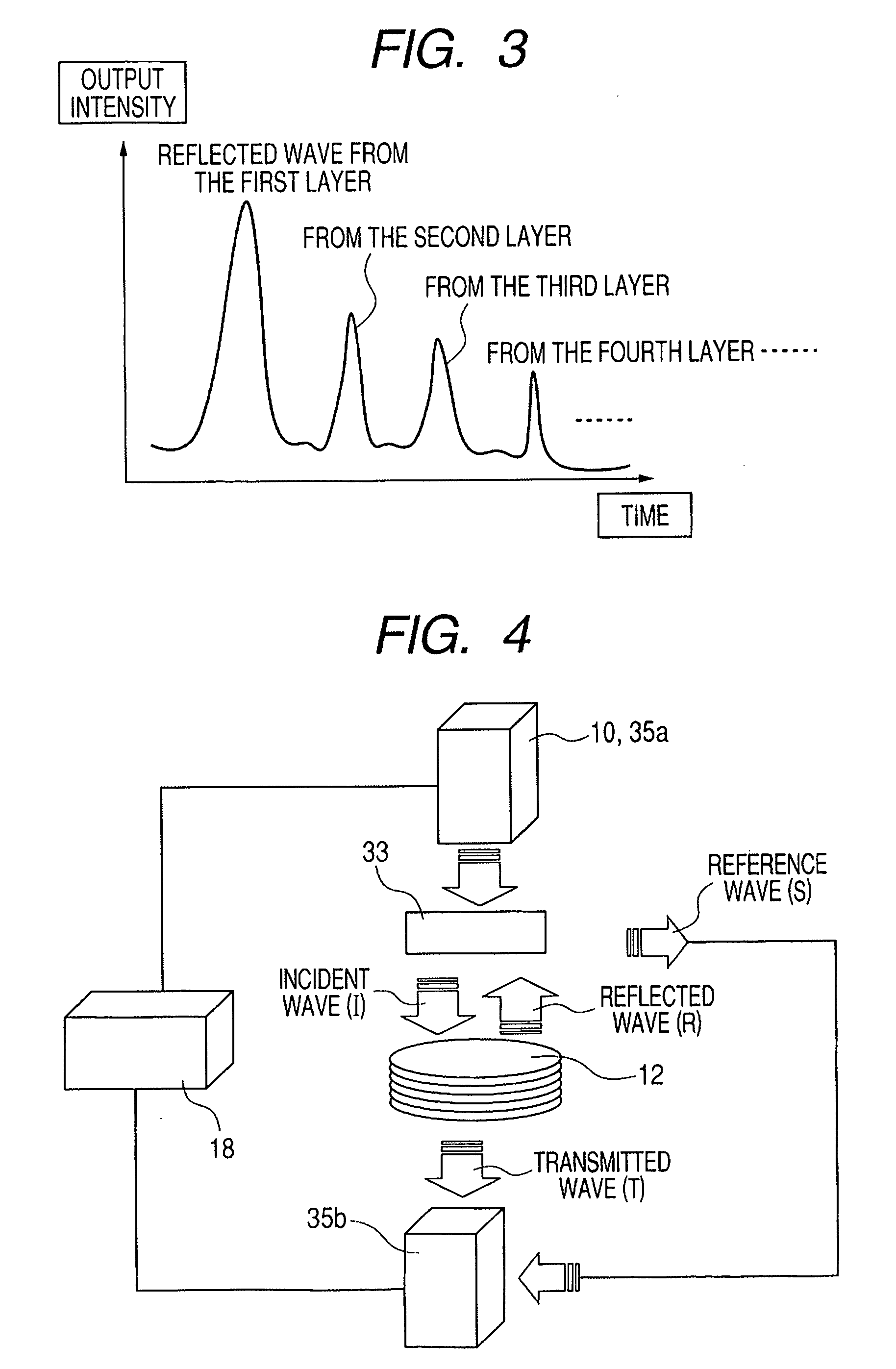
[0040]FIG. 4 is a schematic illustration of the second embodiment of system for counting the number of layers of a multilayer object, using both the reflection method and the transmission method, showing the configuration thereof. An electromagnetic wave emitted from an oscillator 10 is divided into an electromagnetic pulse (incident wave (I)) adapted to strike at least the top surface or the bottom surface of a multilayer object 12 that is in a state where two or more than two layers are laid one on the other and an electromagnetic wave (reference wave (S)) that is directly propagated to second optical receiver 35b without entering the multilayer object 12. The incident wave (I) is partly reflected by the interfaces of the intermediate layers of the multilayer object 12 (to produce reflected waves (R)) and received by first optical receiver 35a. The received voltage signals generated by the reflected waves (R) received by the first optical receiver 35a are delivered to processing u...

embodiment 3

[0052]FIG. 7 is a schematic illustration of a system for counting the number of layers of a multilayer object using a propagation path with the reflection method described above by referring to the first embodiment, showing the configuration thereof. This embodiment differs from the first embodiment only in that the electromagnetic wave emitted from the oscillator 10 is partly or entirely made to be propagated to the optical receiver 15 by way of a propagation path. Otherwise, this embodiment is identical with the first embodiment.

[0053] A specific example of counting the number of sheets of paper that are laid one on the other in air will be discussed below. In this example using the above described reflection method, both the electromagnetic wave that is propagated through air to strike the sheets of paper and the electromagnetic wave that is propagated through air from the surface of the sheets of paper at the side of the optical receiver 15 to the optical receiver 15 are propag...


PUM

PropertyMeasurementUnit
thicknessaaaaaaaaaa
reflectionaaaaaaaaaa
phaseaaaaaaaaaa

Abstract

A system or method for counting the number of layers of a multilayer object is adapted for counting the number of layers by means of a simple arrangement of emitting an electromagnetic wave to strike the object that is in a multilayer state. In the system or method, an electromagnetic wave is caused to strike at least either the top surface or the bottom surface of a multilayer object and electromagnetic waves generated by reflection of the incident electromagnetic wave at the respective interfaces of the layers of the multilayer object or an electromagnetic wave generated by transmission of the electromagnetic wave through the multilayer object.

Description

TECHNICAL FIELD [0001] This invention relates to a system and a method for counting the number of layers of an object in a multilayer state (to be also referred to as multilayer object) on the basis of the electromagnetic signal obtained by irradiating at least either the top surface or the bottom surface of the multilayer object with an electromagnetic wave so as to be reflected by or transmitted through the object. BACKGROUND ART [0002] Some known systems and methods for counting the number of layers of a multilayer object will be described below. FIGS. 9 and 10 illustrate a system and a method that are known for counting the number of layers of a multilayer object formed by laying sheets of a material (Japanese Patent Application Laid-Open No. 2003-44826). FIG. 9 illustrates the configuration of the known counting system. Referring to FIG. 9, the system comprises a first projector 74a for projecting infrared rays that strike a lateral surface of a multilayer object 12 (film) moun...

Claims


Application Information

Patent Timeline
Patent Type & Authority Applications(United States)
IPC IPC(8): G01V3/00G01B15/02G01N21/35G01N21/3563G01N21/3586G01N21/41G01N21/84G01N22/00G06M9/00
CPCG01B15/02G01N21/3581G01N21/3563G01N21/8422G01N2021/8438G01N21/41
Inventor MIYAZAKI, JUNGOOUCHI, TOSHIHIKO
Owner CANON KK
Why Eureka
Try Eureka