Specially coherent optics

a optical field technology, applied in the field of special type of optics, can solve the problems of limiting the ultimate resolution and purity of the image, no optics are perfectly uniform, and the transmission-medium lens is too small, so as to achieve the effect of reducing cost and high precision

Active Publication Date: 2006-11-02
SIMMONS JOHN CASTLE
View PDF7 Cites 78 Cited by
  • Summary
  • Abstract
  • Description
  • Claims
  • Application Information

AI Technical Summary

Benefits of technology

[0034] Improved cameras and display devices, both still and motion, including higher precision, lower cost, and true 3-D enabled.

Problems solved by technology

However, transmissive-medium lenses also have many inherent disadvantages.
This, though clever optics like spatial filtering deals effectively with this, limits the ultimate resolution and purity of the image.
Tooling Precision Difficulties with Scale: Also, no optics are perfectly uniform which adds image aberrations.
This becomes more of a problem as we try to make lenses much larger (such as large telescope lenses) or much smaller (because of the difficulties of tooling tiny lenses).
Coherency Limits: The very method used to warp light selectively limits the depth of field in cameras, glasses, contacts, etc. often leaving areas in front of or beyond the item focused upon “out of focus” This is also an issue with our own eyes that glass glasses do not help with.
Peripheral Vision in Corrective Optics: Glasses, because of their own limitations, do nothing to help the limited human peripheral vision and typically make it worse with the added limitations to field of view and near-edge optic aberration issues.
However, the radial slits, scalloped edges and two spaced-apart concentric circles increase diffraction of light, which in turn reduces the contrast of the image.
These designs suffer from diffraction at the edge of a dark ring or masked area, which detracts from any improvement.
However, though many of the pinhole or light-slice based solutions provide limited fields of vision with sharper images, none of the aforementioned new technologies provide unobstructed clear natural vision with a full natural landscape.
The holes have to be spaced as such because if they are moved closer together, the rays overlap and the effect is lost.
They also provide poor peripheral vision.
Field of view is extremely limited, and peripheral vision is non-existent.
As a practical matter, though initially promising due to their ability to improve vision with an “off-the-shelf” to “one-size-fits-all” optic, they are only usable when sitting still and reading in good light.

Method used


Image

  • Specially coherent optics
  • Specially coherent optics
  • Specially coherent optics

Examples


Embodiment Construction

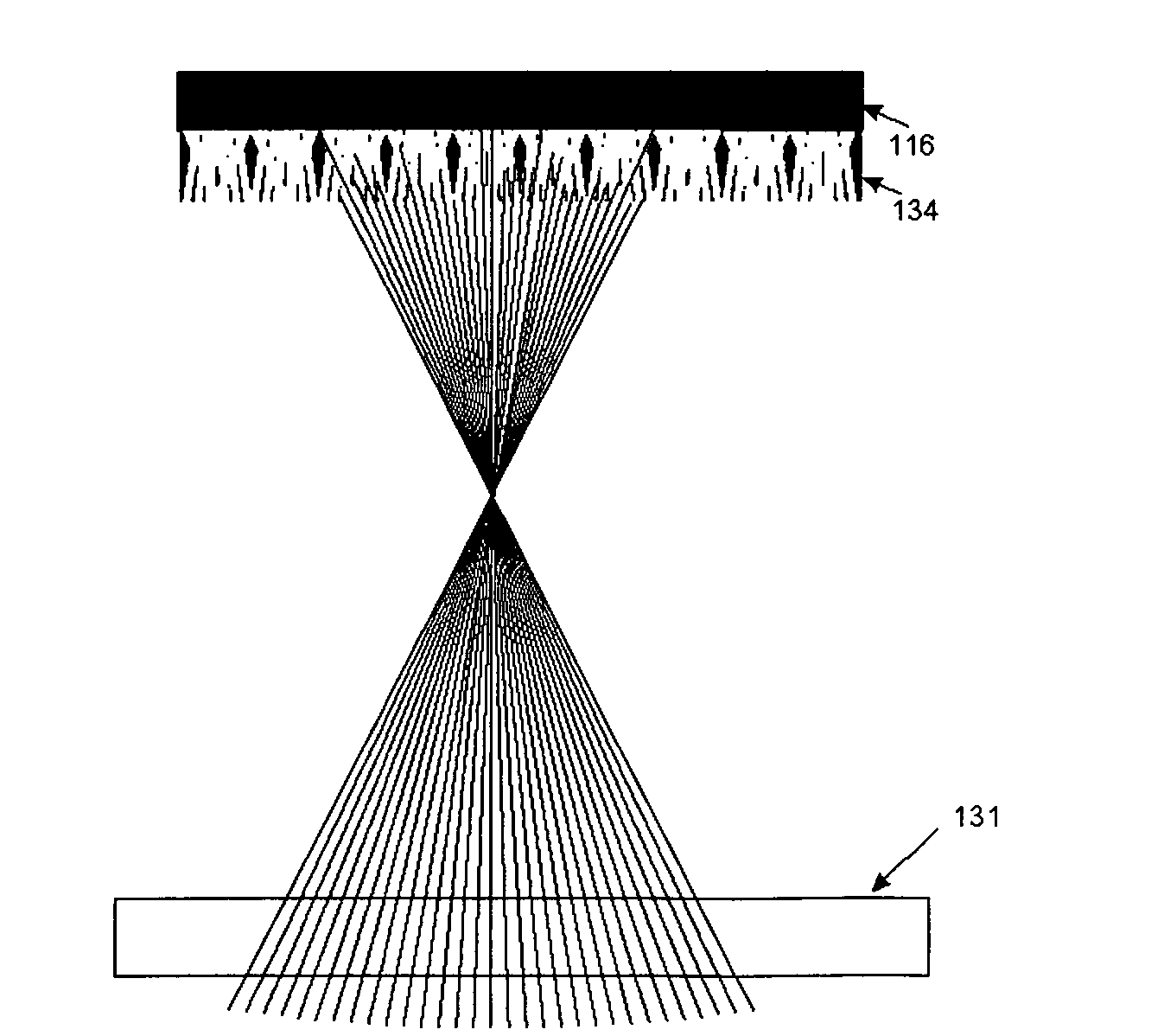
[0040] The use of Channel Mapped Optics (CMO), controls and conditions light in a non-refractive manner to achieve visual effects not practical with refractive or reflective optics.

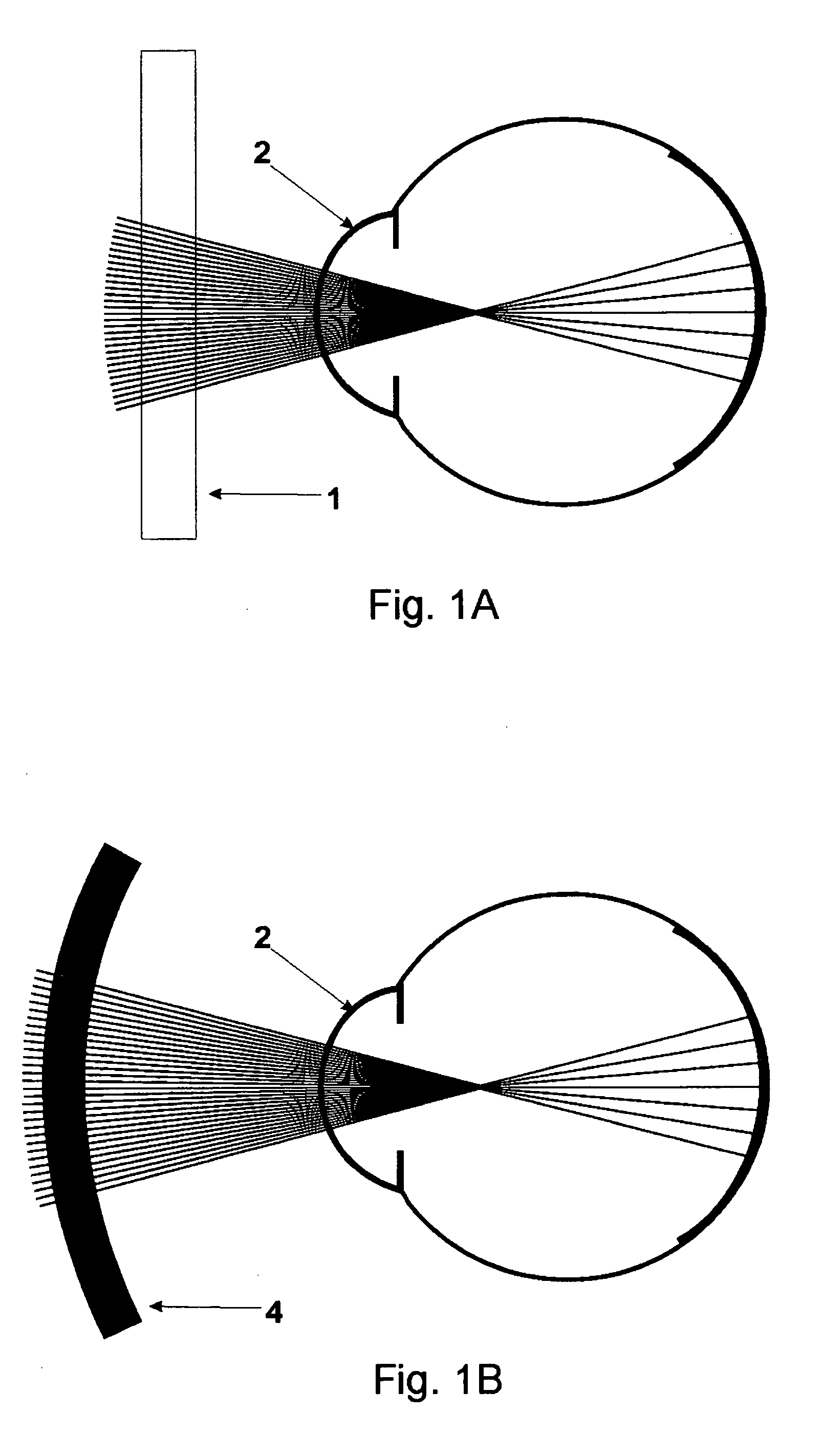
[0041] Aperture Array Alignment with the Eye's Effective Center of Rotation:

[0042] As an example, a worn replacement for glasses superior to the Stenopeic method is first described.

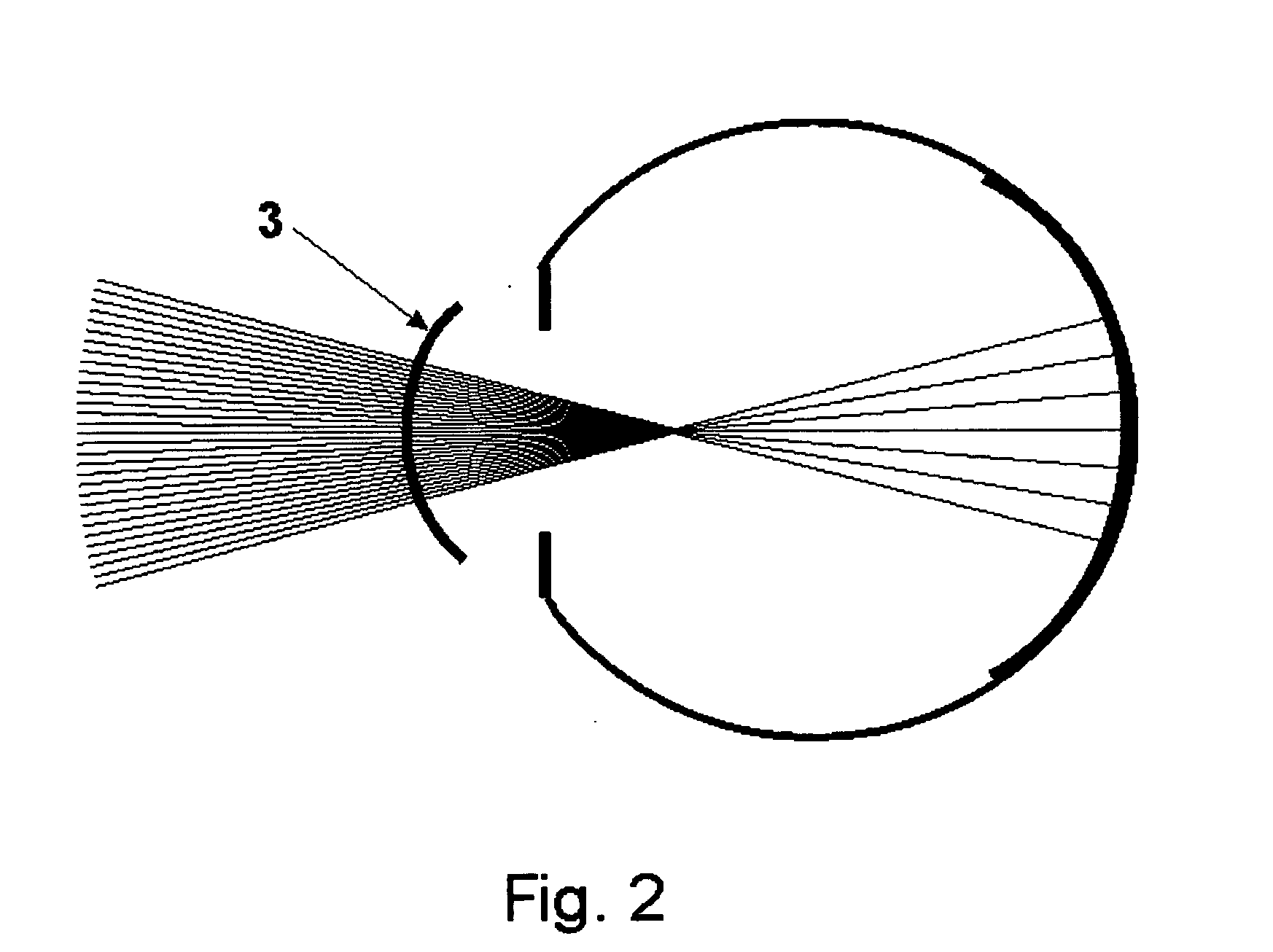
[0043] The array and path of the apertures through the medium are aligned and pointed with respect to the vision-effective rotational axis of the eye so that as the wearer moves his eyes, the apertures continue to be essentially aligned with the optical axis to provide a clear, non-blocked image. This provides a brighter image with the light largely normal to the surface of the cornea (for maximum transmission) and a vastly broader image (full peripheral vision),

[0044] Ex. A: The glasses lens-replacing medium itself, can be curved along a semi-sphere whose approximate center (were it a full sphere) is at or near the rotatio...


PUM


Abstract

A refinement in optics providing images with improved sharpness, better control of depth of field, vision-improvement applications, and 3-D capture and display.

Description

STATEMENT OF RELATED APPLICATIONS [0001] The present application claims the benefit of provisional application 60 / 633,732 which was filed on Dec. 6, 2004 and which is incorporated herein in its entirety.BACKGROUND OF THE INVENTION [0002] Glass lenses to select a single coherent set of photons from a typically chaotic, photons-going-everywhere wave-front of light have been enormously effective. For example, a camera lens selects from said chaotic mess only the photons whose vector to the face of the lens at the point of incidence on that lens fits the current desired focus criteria. Other light, not fitting that criteria identified by the optics, is either less profound on the image plane (and thus overpowered by the preferred light) or selected out by spatial filtering altogether. This has been adequate for a world of applications that make up the very mature field of refractive optics. [0003] However, transmissive-medium lenses also have many inherent disadvantages. [0004] Light Lo...

Claims


Application Information

Patent Timeline
Patent Type & Authority Applications(United States)
IPC IPC(8): G02C7/04
CPCG02C7/16G02B27/46G06F18/00
Inventor SIMMONS, JOHN CASTLE
Owner SIMMONS JOHN CASTLE
Why Eureka
Try Eureka