Circuit protection device

a protection device and circuit technology, applied in emergency protection circuit arrangements for limiting excess voltage/current, emergency protection circuit arrangements, etc., can solve the problem of limiting the capacity of varistor to conduct current, generating heat in excess of what it can satisfactorily dissipate, and ultimately failing, so as to achieve less susceptible to failure

Active Publication Date: 2006-11-02
SCHNEIDER ELECTRIC USA INC
View PDF9 Cites 45 Cited by
  • Summary
  • Abstract
  • Description
  • Claims
  • Application Information

AI Technical Summary

Benefits of technology

[0018] One object of the present invention is to provide a compact and reliable circuit protection device which is less susceptible to a failure caused by excessive heat generated by a voltage sensitive device such as a varistor.

Problems solved by technology

One significant limitation of a varistor is that during a power surge when a varistor is conducting high currents, it will generate heat in excess of what it can satisfactorily dissipate.
The heat is generally proportional to the area of the varistor as well as the wave shape of the current and is a limiting factor in the capability of the varistor to conduct current.
If an over-voltage condition is not timely discontinued, the varistor can continue to increase in temperature and can ultimately fail, i.e., rupture or explode.
It is possible for such a failure to destroy nearby electronic components and equipment.
The failure of a varistor in a surge suppression system may allow the fault condition to reach the sensitive electronic equipment the system was designed to protect.
However, the structures disclosed in Martenson et. al. require a number and type of components, and arrangement of those components, that would appear to complicate construction and operation of the circuit protection device.

Method used


Image

  • Circuit protection device
  • Circuit protection device
  • Circuit protection device

Examples


Embodiment Construction

[0036] While the present invention is capable of embodiment in many different forms, there is shown in the drawings and will herein be described in detail exemplary embodiments of the invention with the understanding that the present disclosure is to be considered as an exemplification of the principles of the invention and is not intended to limit the broad aspect of the invention to the embodiments illustrated. Like parts used in the various embodiments disclosed may use the same reference numbers unless otherwise stated.

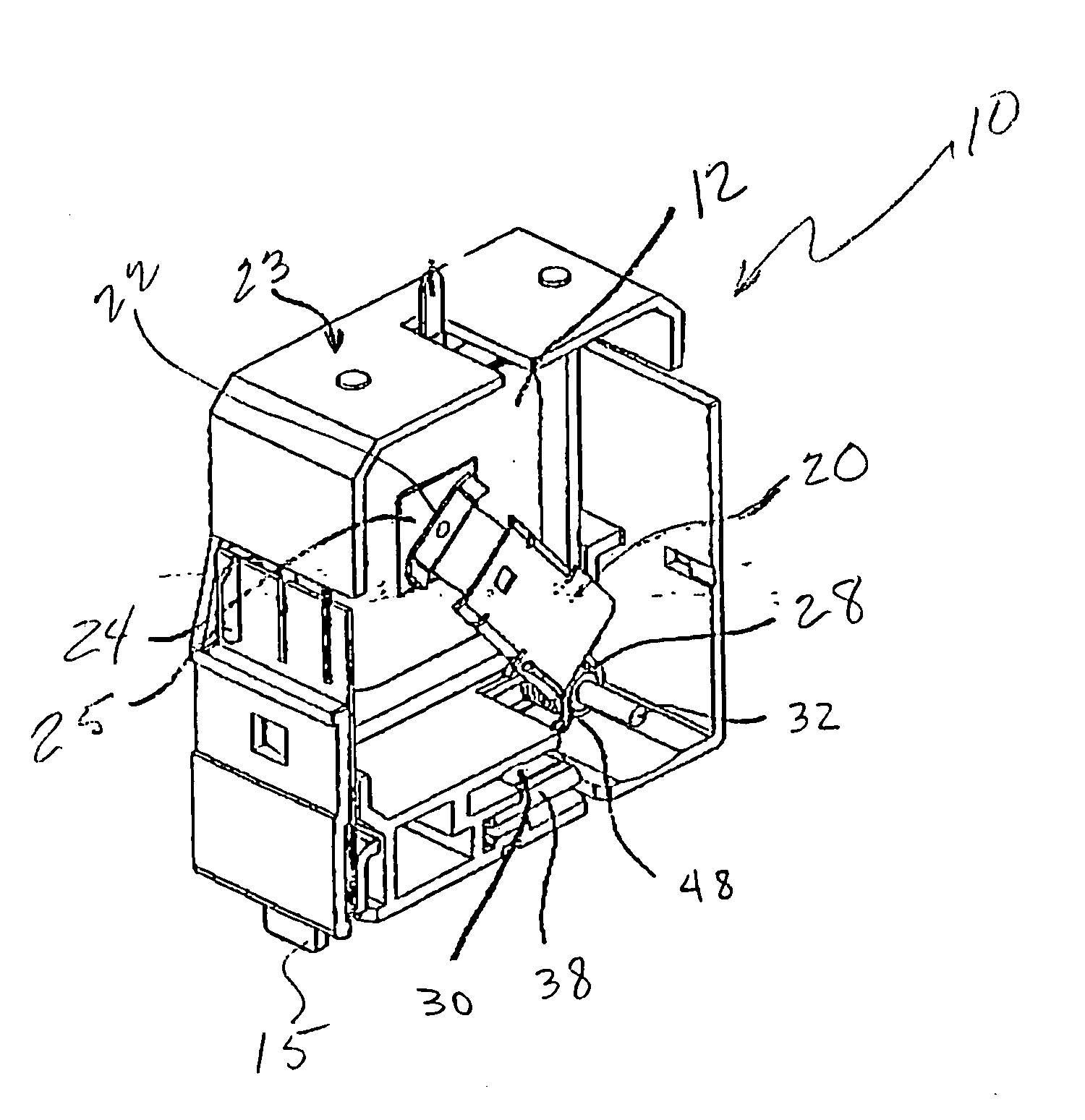
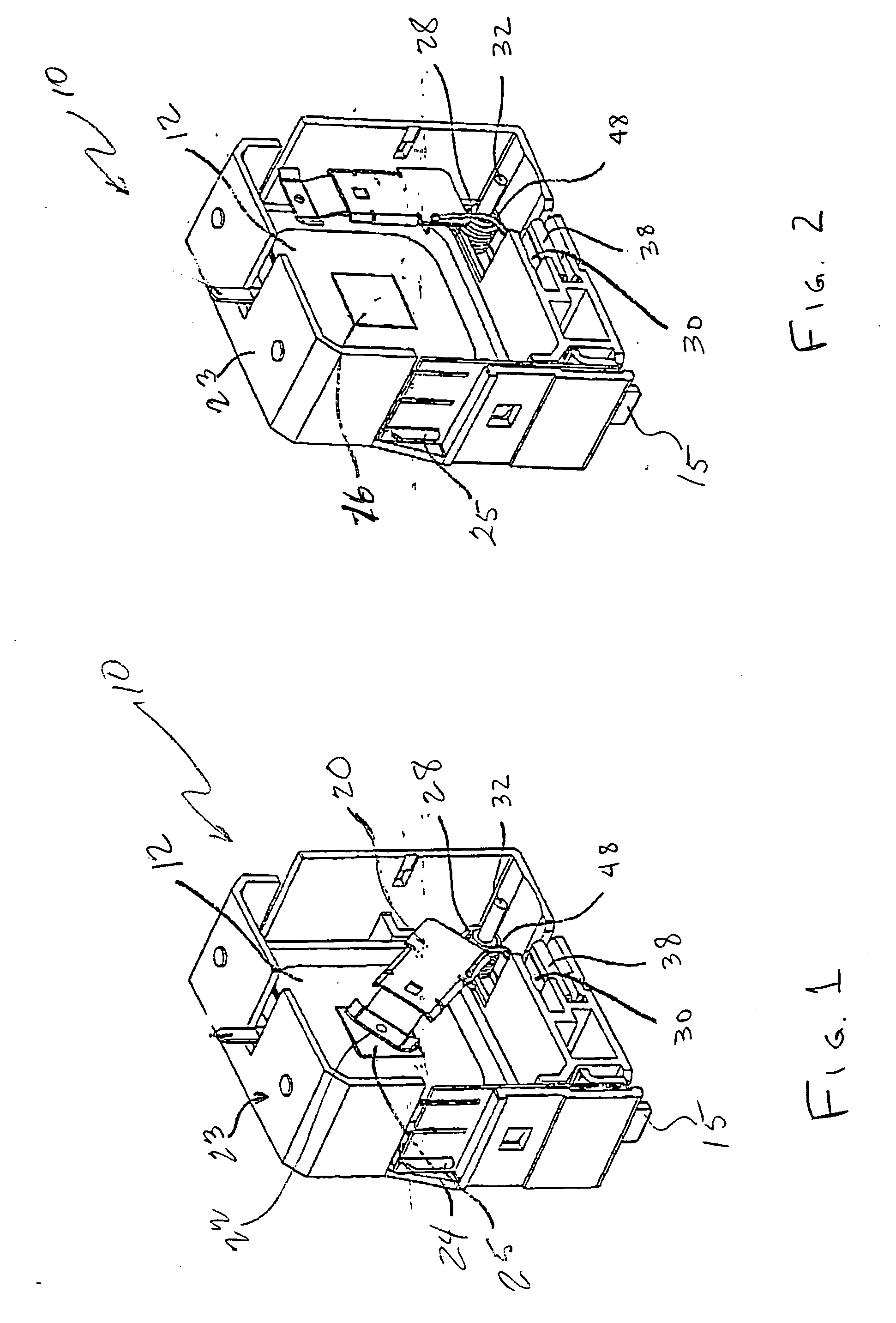
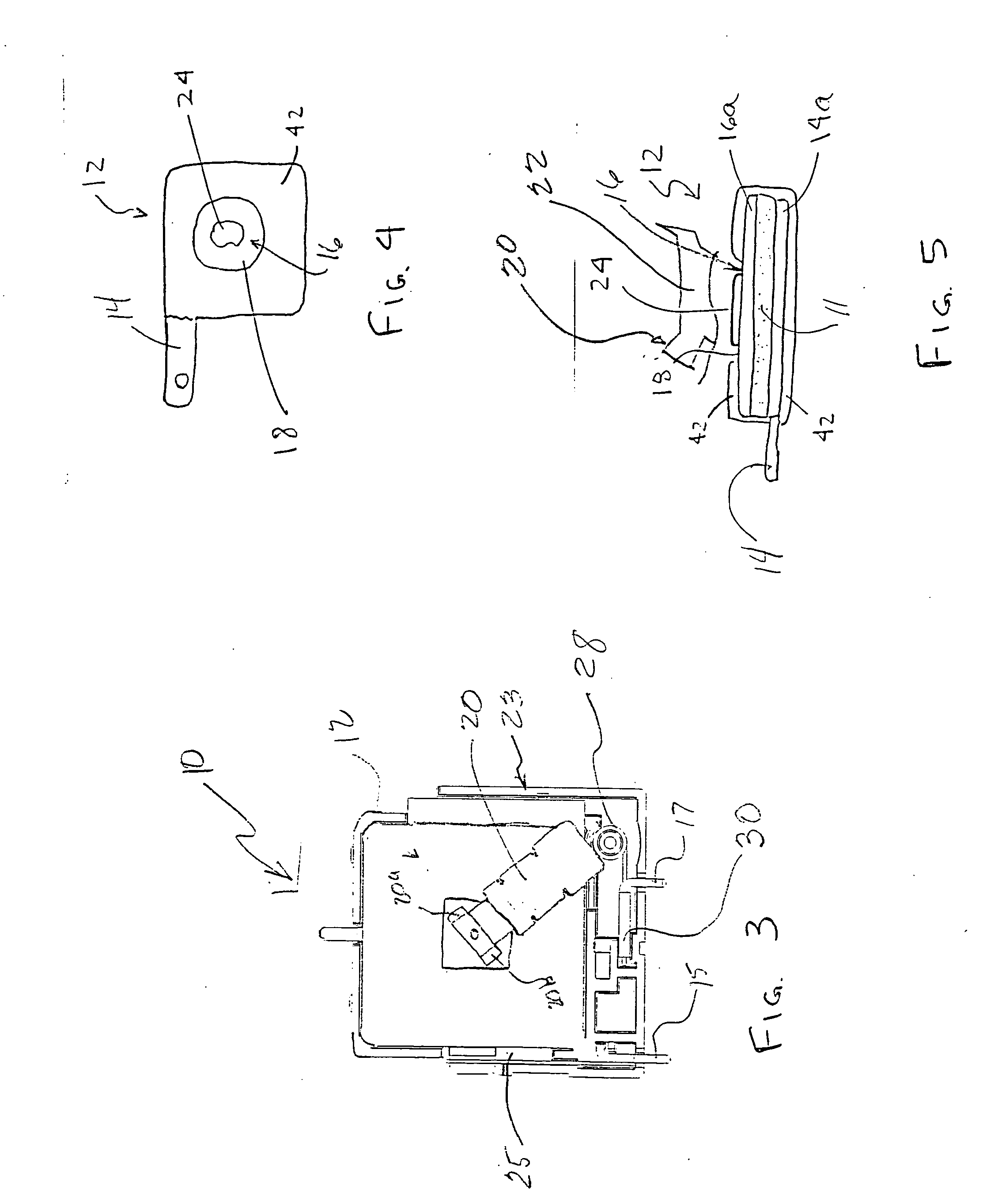
[0037]FIGS. 1-6 disclose a circuit protection device 10 according to one embodiment of the invention. The circuit protection device 10 includes a voltage sensitive element 12, a conductor arm 20, a thermal connector 24, a spring 28, a first common terminal 25, a second common terminal 30 (see also FIG. 14), a housing 23, and terminals 15 and 17 extending from the housing for connecting the circuit protection device 10 to a circuit to be protected.

[0038]FIGS. 4 a...


PUM


Abstract

A circuit protection device including a conductor arm releasably connected between a voltage sensitive device and a circuit to be protected. The connector arm is biased to move in a direction generally parallel with a plane defined by a lateral dissection between the releasably connected conductor arm and the voltage sensitive device.

Description

TECHNICAL FIELD [0001] The present invention relates to overvoltage protection devices for electrical circuits and equipment; and more specifically, to a circuit protection device. BACKGROUND OF THE INVENTION [0002] Electronic protection devices such as voltage surge protectors are commonly used to protect electric or electronic equipment such as PLCs, computers, and entire electrical installations against destructive overvoltage surges. Such surge protection devices guard the electronic circuitry against detrimental power surges generated from various sources, including, but not limited to: motors, transformers, welding machines, lightning strikes, and power-grid-switching by the energy supplier. To protect against unacceptable voltage surges, voltage sensitive devices are employed to absorb or shunt current safely away from a circuit to be protected. [0003] A very useful voltage sensitive device is a varistor such as a metal oxide varistor (MOV). MOVs are solid-state surge protect...

Claims


Application Information

Patent Timeline
Patent Type & Authority Applications(United States)
IPC IPC(8): H02H9/00
CPCH01C7/126
Inventor ASZMUS, GREGORY P.
Owner SCHNEIDER ELECTRIC USA INC
Why Eureka
Try Eureka