Temperature-detecting and control circuit

a control circuit and temperature detection technology, applied in the field of temperature detection and control circuits, can solve the problems of reducing the operating efficiency of the computer system, destroying devices, and creating surges in the operational temperature of the computer, so as to achieve less noise, improve heat dissipation efficiency, and simplify the control process

Inactive Publication Date: 2006-11-02
ASUSTEK COMPUTER INC
View PDF6 Cites 7 Cited by
  • Summary
  • Abstract
  • Description
  • Claims
  • Application Information

AI Technical Summary

Benefits of technology

[0006] One aspect of the present invention provides a temperature-detecting and control circuit with simpler and cheaper devices to control the dissipation of waste heat in an electronic unit.
[0008] The third aspect of the present invention provides a temperature-detecting and control circuit having a fan rotary controller that can accomplish the requirements of making the fan generate less noise and dissipate heat more efficiently.
[0010] The fifth aspect of the present invention provides temperature-detecting and control circuit that can provide both a GPU circuit and a memory device circuit that are set in the same electronic unit to control the working voltages for either increasing the operation speed or decreasing heat generating of the same.
[0020] The first advantage is that the temperature detecting and control circuit can simplify the process for controlling the temperature of an electronic unit. The second advantage is that the temperature detecting and control circuit can inform the operator whether a graphic card set in a computer system operates within a allowable temperature to prevent the graphic card from being burned out. The third advantages is that the temperature detecting and control circuit has a fan rotary controller that can accomplish the requirements of making the fan generating less noise and dissipating heat more efficiently. The fourth advantage is that the temperature detecting and control circuit having a fan rotary controller is used to control a fan rotating in two rotary speeds by a voltage dividing method. The controller merely consists of several transistor and resistors, which can approach the desired functions in a chipper way. The fifth advantage is that the temperature detecting and control circuit providing voltage controlling functions for both a GPU power circuit and a memory power circuit set in the same GPU to control their working voltages for either increasing the operation speed or decreasing heat generation of the same.

Problems solved by technology

Waste heat generated by electronic devices in a small volume creates surges in the operational temperature of a computer.
This situation reduces the operating efficiency of the computer system, or may damage devices therein.
However, the temperature detecting-chip and a plus width modulation (PWM) circuit used for controlling the rotation of the fan are very expensive, and the temperature detected by the chip generally is imprecise.

Method used


Image

  • Temperature-detecting and control circuit
  • Temperature-detecting and control circuit
  • Temperature-detecting and control circuit

Examples


Embodiment Construction

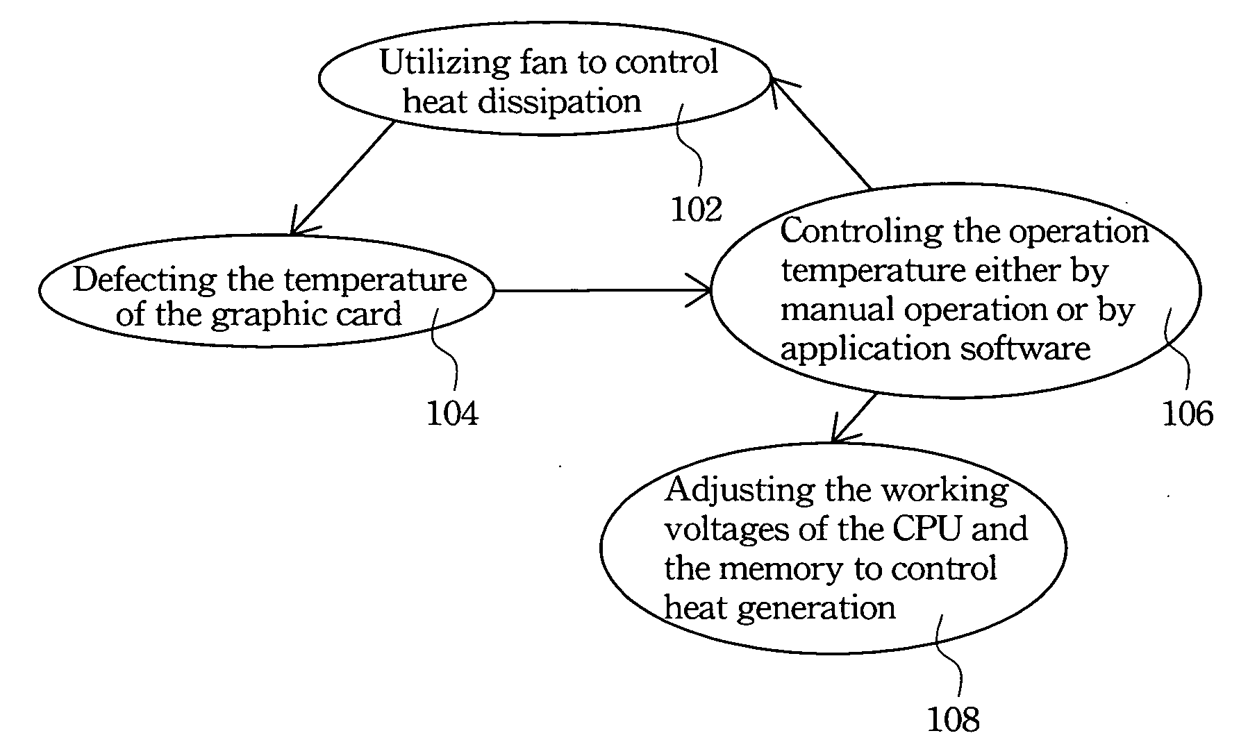
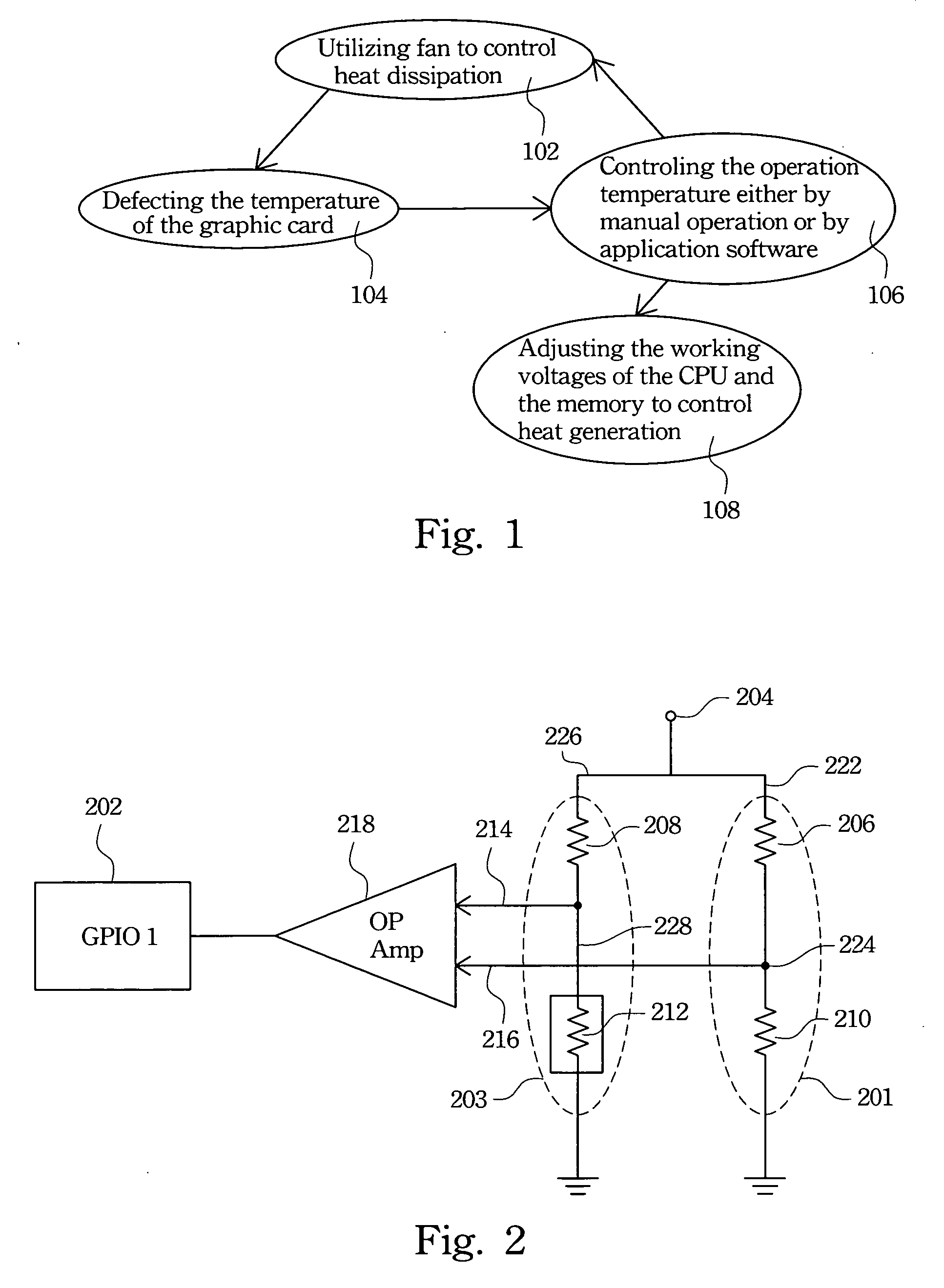
[0029]FIG. 1 is a functional diagram illustrating the functions of the temperature detecting and control circuit, in accordance with one preferred embodiment of the present invention.

[0030] Referring to stage 104, a temperature of an electronic unit, such as a graphic card set in a computer system, is detected by the temperature detecting and control circuit. Next, the temperature detecting and control circuit is controlled, either by manual operation or by application software (referring to stage 106). Then, the operation temperature is controlled via utilizing a fan rotating at various speeds for controlling the heat dissipation (referring to stage 102) or adjusting the working voltages of the graphic card and a memory for controlling heat generation (referring to stage 108).

[0031]FIG. 2 is a circuit diagram illustrating the circuit arrangement of the temperature detecting and control circuit, in accordance with the first preferred embodiment of the present invention. In the cir...


PUM


Abstract

A temperature detecting and control circuit with a first voltage dividing circuit, a second voltage dividing circuit, a fan rotary speed controller, and a comparator is described. The first voltage dividing circuit generates a first voltage. The second voltage dividing circuit generates a second voltage. The second voltage dividing circuit has a temperature sensitive element for detecting the temperature of hardware. The comparator compares the first voltage with the second voltage and then outputs the result to the fan rotary speed controller. When the fan rotary speed controller receives a first fan control signal, the fan is maintained at a first rotary speed. When the fan rotary speed controller receives a second fan control signal, the fan is maintained at a second rotary speed.

Description

RELATED APPLICATIONS [0001] The present application is based on, and claims priority from, Taiwan Application Serial Number 94114007, filed Apr. 29, 2005, the disclosure of which is hereby incorporated by reference herein in its entirety. FIELD OF THE INVENTION [0002] The present invention relates to a temperature detecting and control circuit, and more particularly, relates to a temperature detecting and control circuit applied in a computer system. BACKGROUND OF THE INVENTION [0003] Currently, computers are designed to be as small as possible, with increasingly fast operation speeds. Waste heat generated by electronic devices in a small volume creates surges in the operational temperature of a computer. This situation reduces the operating efficiency of the computer system, or may damage devices therein. Accordingly, computer operation temperature control is vital to the functionality of the computer. [0004] A traditional graphic card in a computer system usually processes image d...

Claims


Application Information

Patent Timeline
Patent Type & Authority Applications(United States)
IPC IPC(8): H02H5/04
CPCG06F1/20
Inventor CHANG, CHIEN-LUNGKAO, KUO-CHUNG
Owner ASUSTEK COMPUTER INC
Why Eureka
Try Eureka