Fluid mixing apparatus

a technology of mixing apparatus and fluid, which is applied in lighting and heating apparatus, combustion types, separation processes, etc., can solve the problems of excessive urea water waste, failure to decompose nox parts, and need to perform extra treatment, etc., and achieve the effect of suppressing the pressure loss of the first fluid

Inactive Publication Date: 2006-11-02
HITACHI HIGH-TECH CORP +1
View PDF99 Cites 71 Cited by
  • Summary
  • Abstract
  • Description
  • Claims
  • Application Information

AI Technical Summary

Benefits of technology

[0009] Further, in a mixing apparatus for mixing the exhaust gas and the intake air for the EGR, as well as even mixing of the exhaust gas and the intake air in a small space, suction of the exhaust gas while suppressing the pressure loss of an intake air system as much as possible is required.
[0027] According to the above aspects of the present invention, in conveying and mixing the first fluid and the second fluid, the first fluid and the second fluid can be evenly mixed in a small space by suctioning only the necessary amount of the second fluid while suppressing the pressure loss of the first fluid as much as possible.

Problems solved by technology

If the ratio of ammonia is smaller than this ratio, a part of NOx fails to be decomposed due to the shortage of ammonia.
As a result, an excessive portion of the urea water is wasted, and an extra treatment needs to be performed to prevent ammonia from being discharged outside.

Method used


Image

  • Fluid mixing apparatus
  • Fluid mixing apparatus
  • Fluid mixing apparatus

Examples


second embodiment

[0076]FIG. 4 is a perspective view of a fluid mixing apparatus according to a second embodiment of the present invention. FIG. 5A is a front view of the fluid mixing apparatus. FIG. 5B is a cross-sectional view of the fluid mixing apparatus cut along the VB-VB line shown in FIG. 5A. The components and objects of the present embodiment having the similar functions as the components and objects of the first embodiment are indicated by the same reference numerals, and description thereof will be omitted.

[0077] The second embodiment is different from the first embodiment in that the interior of the flow passage 11 is divided by a flat plate 18 and a divider plate 20, which are perpendicular to the axis line of the flow passage 11, and that four internal cylinders 19 are connected to the flat plate 18 and the divider plate 20. The flat plate 18 divides the flow passage 11 at an upstream position of a connecting position of the flow passage 12, and has four openings. The divider plate 20...

third embodiment

[0083]FIG. 6 is a perspective view of a fluid mixing apparatus according to a third embodiment of the present invention. FIG. 7A is a front view of the fluid mixing apparatus. FIG. 7B is a cross-sectional view of the fluid mixing apparatus cut along the VIIB-VIIB line shown in FIG. 7A. The components and objects of the present embodiment having the similar functions as the components and objects of the foregoing embodiments are indicated by the same reference numerals, and description thereof will be omitted.

[0084] The present embodiment is different from the first embodiment in that the swirl-generating stator 15 is directly joined to the inner circumferential surface of the flow passage 11, and that the internal cylinder 13 is not provided. The present embodiment is further different from the first embodiment in that the openings 16 serving as the inlets for the fluid 2 are formed on the wall surface of the flow passage 11, and that a ring-shaped duct 21, which serves as the head...

fourth embodiment

[0088]FIG. 8 is a perspective view of a fluid mixing apparatus according to a fourth embodiment of the present invention. FIG. 9A is a front view of the fluid mixing apparatus. FIG. 9B is a cross-sectional view of the fluid mixing apparatus cut along the IXB-IXB line shown in FIG. 9A. The components and objects of the present embodiment having the similar functions as the components and objects of the foregoing embodiments are indicated by the same reference numerals, and description thereof will be omitted.

[0089] The present embodiment is different from the third embodiment in that each of vanes forming a swirl-generating stator 22 is not formed by a flat plate but has a curvature, that the vanes are not joined with one another at the central axis side but are independently joined to the inner circumferential surface of the flow passage 11, and that the number of the vanes is six.

[0090] The curvature of each of the vanes forming the swirl-generating stator 22 is set to convex a s...


PUM

PropertyMeasurementUnit
angleaaaaaaaaaa
angleaaaaaaaaaa
angleaaaaaaaaaa

Abstract

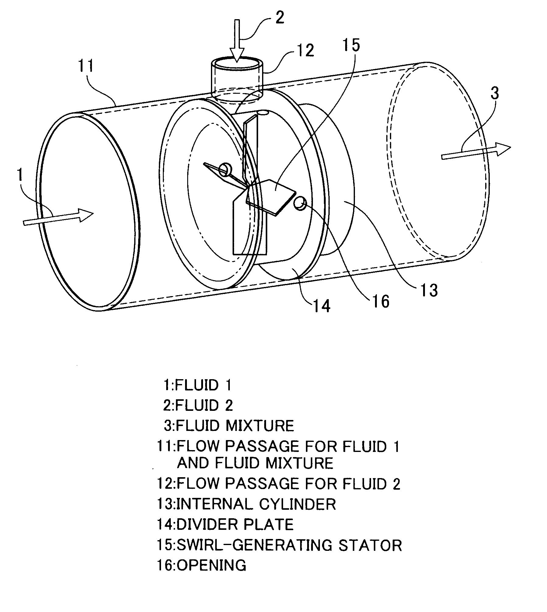
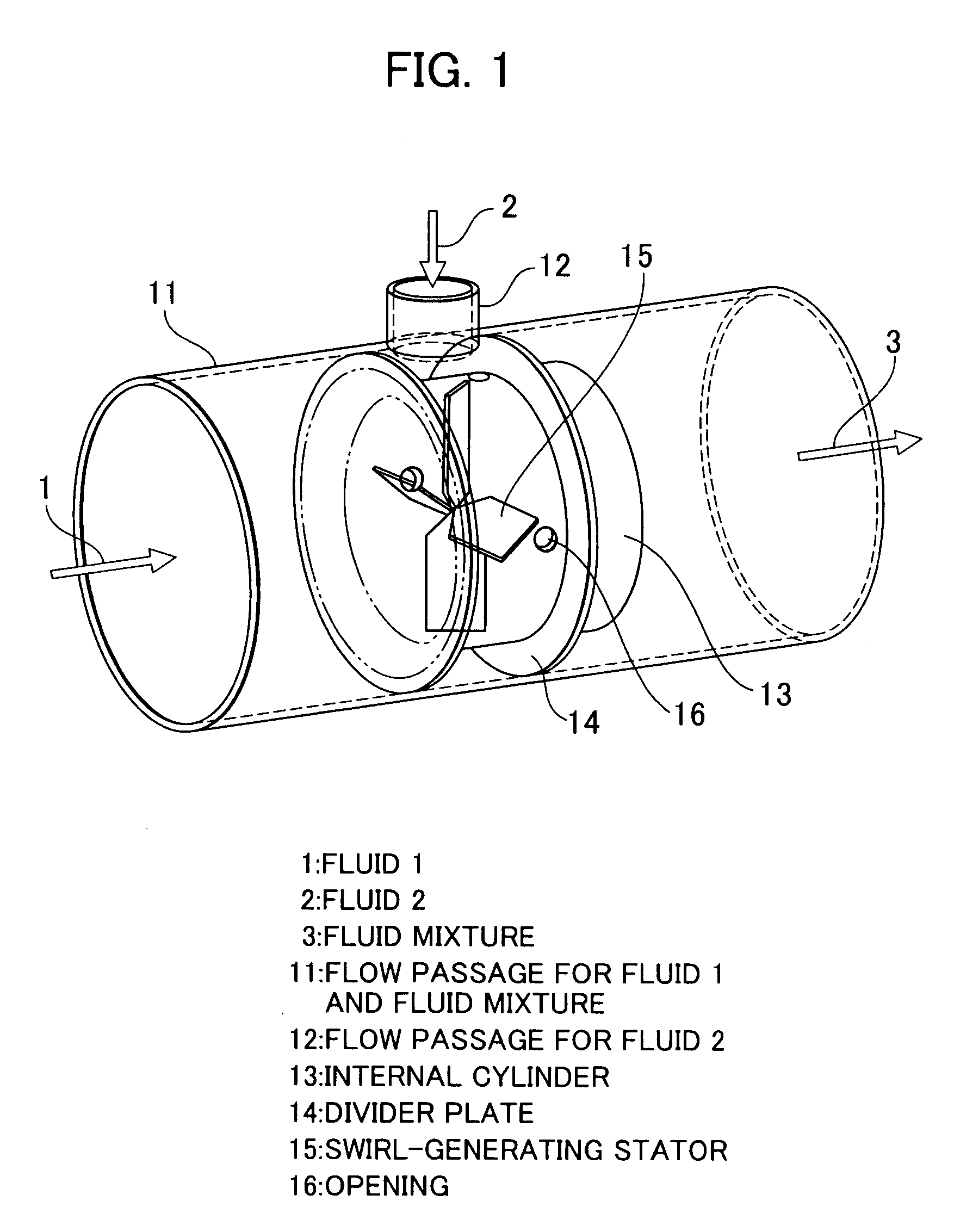
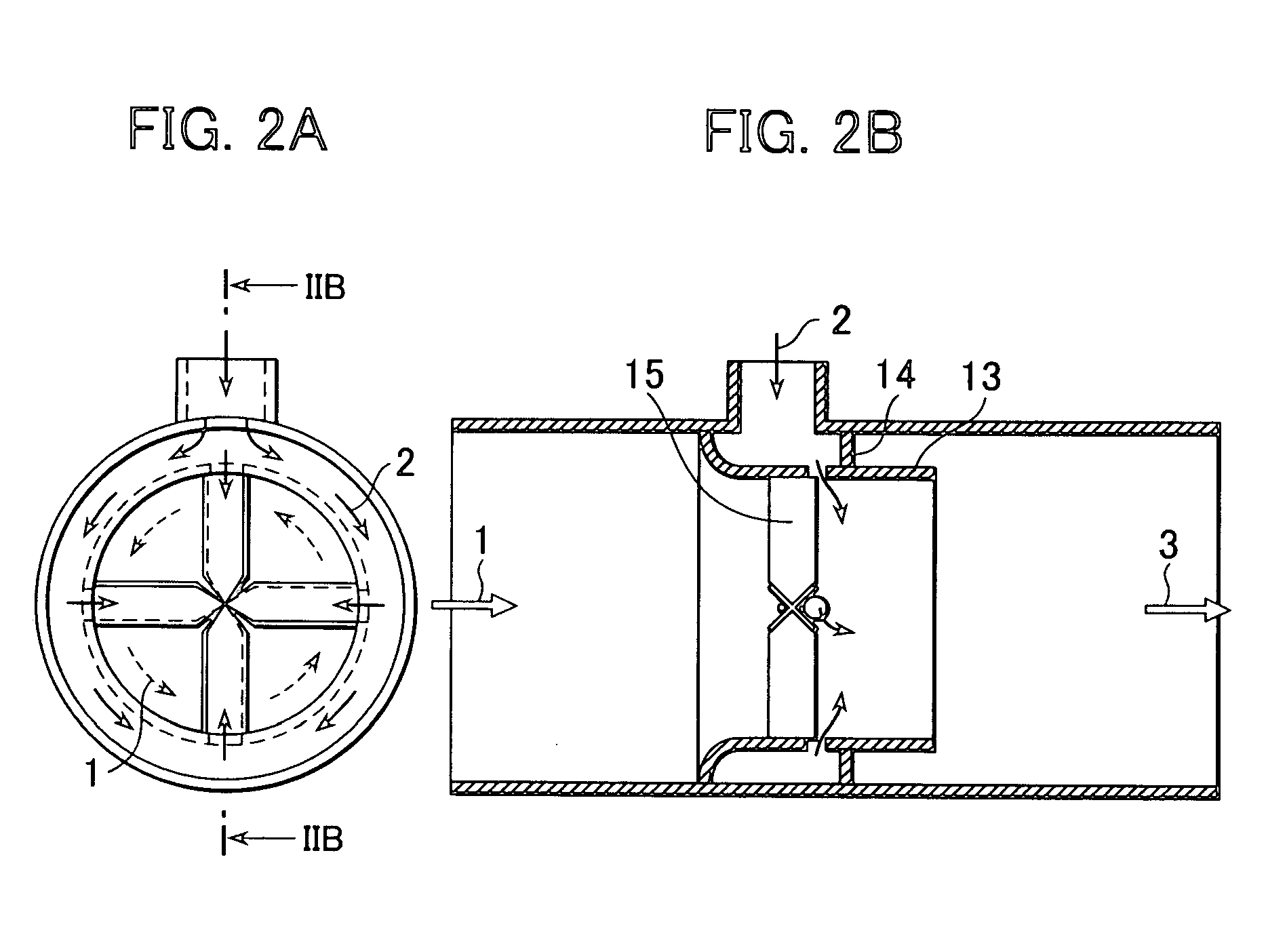
A cylinder-shaped flow passage in which a first fluid flows includes an internal cylinder which is smaller in diameter than the flow passage. A swirl-generating stator having four vanes is radially fixed in the internal cylinder. A header space for supplying a second fluid is provided to the outer circumference of a wall surface of the internal cylinder in contact with flow separation areas which are formed along downstream surfaces of the swirl-generating stator as the first fluid runs into the swirl-generating stator. The wall surface of the internal cylinder is formed with openings through which the flow separation areas communicate with the header space. The second fluid supplied into the header space flows through the openings into the flow separation areas, and is diffused along the vanes of the swirl-generating stator to be swirled and mixed into the first fluid applied with swirling force by the swirl-generating stator.

Description

BACKGROUND OF THE INVENTION [0001] 1. Field of the Invention [0002] The present invention relates to an apparatus for mixing two fluids, and more particularly to a fluid mixing apparatus for mixing two fluids while passing the two fluids therethrough. [0003] 2. Description of the Related Arts [0004] In such devices as a NOx reduction device which reduces NOx contained in an exhaust gas in an internal combustion engine by dosing a reductive gas to the exhaust gas, an EGR device which controls the combustion characteristic of the internal combustion engine by mixing a recirculated exhaust gas into intake air of the internal combustion engine, and a combustor which mixes a gas-turbine fuel and air, a plurality of gases need to be mixed while they pass through the devices. In a diesel engine, for example, NOx is inevitably generated in a thermally efficient, high-temperature combustion. Thus, an aftertreatment is performed in which a reductant is dosed into the exhaust gas to decompose ...

Claims


Application Information

Patent Timeline
Patent Type & Authority Applications(United States)
IPC IPC(8): B01F5/06B01F15/00B01F23/10
CPCB01D53/8631B01F5/0415B01F5/0428B01F5/061B01F2005/0017F23R3/286B01F2215/0422F23D14/64F23J15/003F23R3/14B01F2005/0441Y10T137/87652Y10T137/87587B01F2025/913B01F25/312522B01F25/3121B01F25/31242B01F25/431
Inventor NISHIOKA, AKIRAAMOU, KIYOSHISUKEGAWA, YOSHIHIROKOWATARI, TAKEHIKOHAMADA, YASUNAGAHAMADA, IKUHISAMUKAI, TOSHIFUMITAGUCHI, YOSHINORIYOKOTA, HIROSHI
Owner HITACHI HIGH-TECH CORP
Why Eureka
Try Eureka