
Surgical microscopy system and method for performing eye surgery

a microscopy and eye surgery technology, applied in the field of surgical microscopy system for performing eye surgery, can solve the problems of inexperienced surgeons and difficulty in putting sutures on with a sufficient regularity, and achieve the effect of improving success and precise cuts and other manipulations

Active Publication Date: 2006-11-02
CARL ZEISS MEDITEC AG
View PDF3 Cites 88 Cited by
  • Summary
  • Abstract
  • Description
  • Claims
  • Application Information

AI Technical Summary

Benefits of technology

[0010] The pattern can be for example a circle pattern that can serve as a guiding line for the operating surgeon for placing an incision in the lens capsule of the operated eye. However, the pattern can also be a pattern, other than a circle pattern that can assist the operating surgeon in another respect.
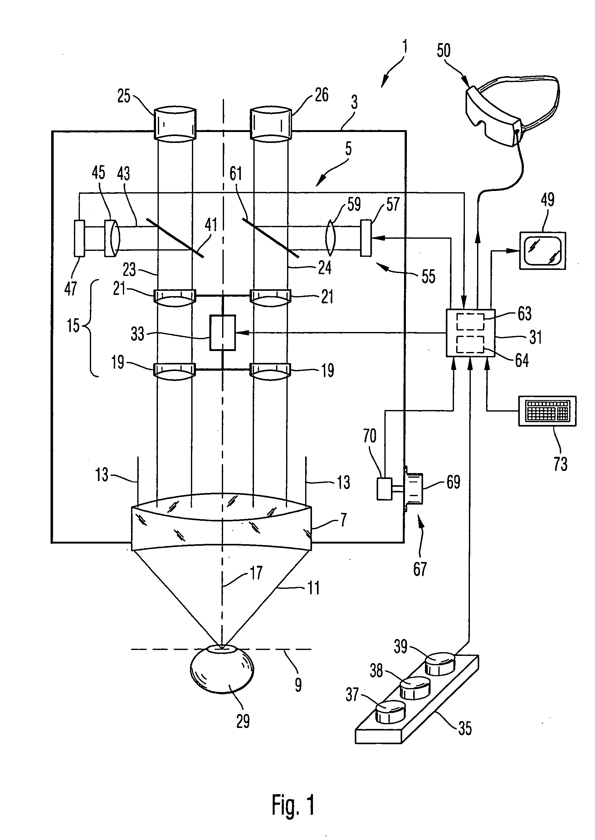
[0011] According to an embodiment of the present invention, the surgical microscopy system comprises an eye-tracker in order to detect a position of the operated eye in the image, and to adapt a position of the superimposed pattern relative to the image in dependence of the detected position of the eye in the image. In particular, the position of the pattern in the image can be fixedly maintained relative to the image of the eye.
[0013] By using the eye-tracker that produces a position signal in dependence of the detected position of the eye, and by configuring the pattern generator such that the pattern generator changes the position of the pattern in the image in dependence of the position signal, it is possible to achieve a more precise cuts and other manipulations on the eye under surgery. Still, the representation of the eye will continuously be displaced within the image due to the application of forces exerted by the surgical tools. However, due to the function of the eye-tracker in combination with the pattern generator, the superimposed pattern will be displaced in correspondence with the displacements of the image of the eye, and the surgeon can achieve a better success by tolerating the permanent displacements of the pattern relative to the image.
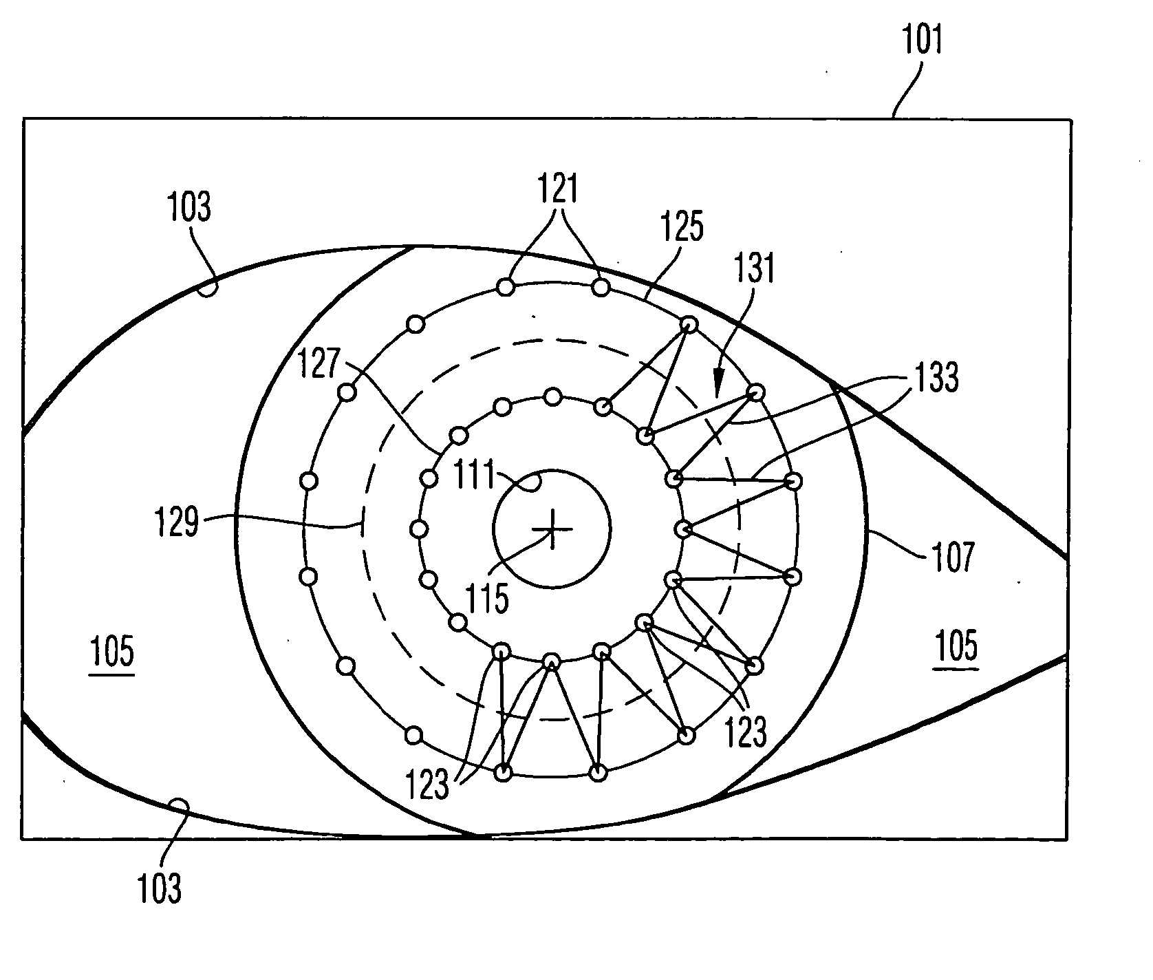
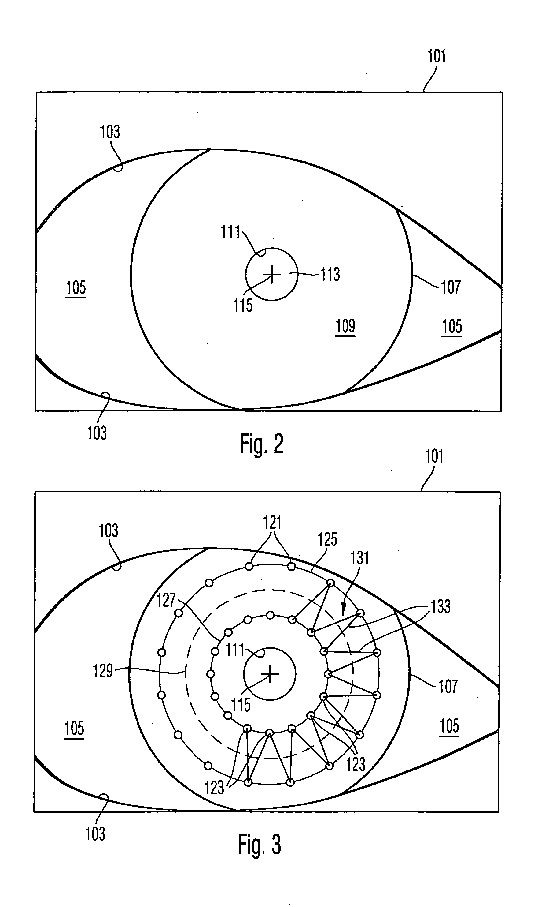
[0017] The interface may comprise a first interface portion for inputting diameters of the first and second circles. Furthermore, the interface may comprise a second interface portion for inputting a number of the pattern elements of the first group or the number of the pattern elements of the second group. Further, the interface may comprise a third interface portion for inputting a circumferential position of the pattern elements of the first group relative to a circumferential position of the pattern elements of the second group. In this way different suture types, such as a zigzag type suture and a suture that comprises a multiplicity of stitches extending in a radial direction, can be easily predefined.

Problems solved by technology

In particular for a relatively inexperienced surgeon it is difficult to place the stitches of the suture with a sufficient regularity.

Method used


Image

  • Surgical microscopy system and method for performing eye surgery
  • Surgical microscopy system and method for performing eye surgery
  • Surgical microscopy system and method for performing eye surgery

Examples


Embodiment Construction

[0035] In the exemplary embodiments described below, components that are alike in function and structure are designated as far as possible by alike reference numerals. Therefore, to understand the features of the individual components of a specific embodiment, the descriptions of other embodiments and of the summary of the invention should be referred to.

[0036]FIG. 1 schematically illustrates a surgical microscopy system 1. The surgical microscopy system 1 comprises a housing body 3 for mounting microscopy optics 5. The microscopy optics 5 comprises an objective lens 7 transforming an object-side divergent beam 11 emanating from an object plane 9 of the objective lens 7 into an image-side parallel beam 13. A pair of zoom systems 15, each comprising groups 19 and 21 of lenses which are displaceable in a direction of an optical axis 17 of the objective lens 7, supply two partial beams 23 and 24 of the image-side parallel beam 13 to oculars 25 and 26. The operating surgeon can look wi...


PUM


Abstract

A surgical microscopy system comprises microscopy optics for generating an image of an eye under surgery. A pattern generator generates a pattern to be superimposed with the image. An eye-tracker is provided for tracking a position of the superimposed pattern with respect to the image in case of a movement of the eye. The superimposed pattern comprises pattern elements that are equally distributed on first and second circles of different sizes, in order to give assistance when placing a suture during a corneal transplant. The superimposed pattern may also provide an assistance for orientating a toric intra-ocular lens.

Description

BACKGROUND OF THE INVENTION [0001] 1. Field of the Invention [0002] The present invention relates to a surgical microscopy system for performing eye surgery. The invention also relates to a method of performing a surgery on the eye. Further, the invention relates to a method of preparing a surgery on the eye. [0003] 2. Brief Description of Related Art [0004] An example of an eye surgery is a corneal transplantation. In such surgery, an original cornea is removed within a circular region, and a corresponding circular graft is inserted to replace the removed cornea. The inserted graft is sewn to the remaining natural cornea. A corresponding suture should be set with regular stitches, in order to not disturb a symmetry of the eye. In particular for a relatively inexperienced surgeon it is difficult to place the stitches of the suture with a sufficient regularity. [0005] Another example of an eye surgery is a cataract surgery. In a cataract surgery, the natural lens of the human eye, in...

Claims


Application Information

Patent Timeline
IPC IPC(8): A61F9/013A61B3/10
CPCA61B3/107A61B3/13A61B3/113
Inventor MOELLER, GERHARDSEIWERT, ANJAPEREZ, MICHELAMEND, PETER
Owner CARL ZEISS MEDITEC AG
Learn More