
Remotely operable vehicle disabling system

a remote-operated, vehicle technology, applied in the direction of ignition automatic control, electric controllers, instruments, etc., can solve the problems of serious risk that the operator can speed off, street and highway chases, and continual risk, and achieve the effect of inhibiting the driver

Inactive Publication Date: 2006-11-09
PUAMAU SOANE R
View PDF15 Cites 94 Cited by
  • Summary
  • Abstract
  • Description
  • Claims
  • Application Information

AI Technical Summary

Benefits of technology

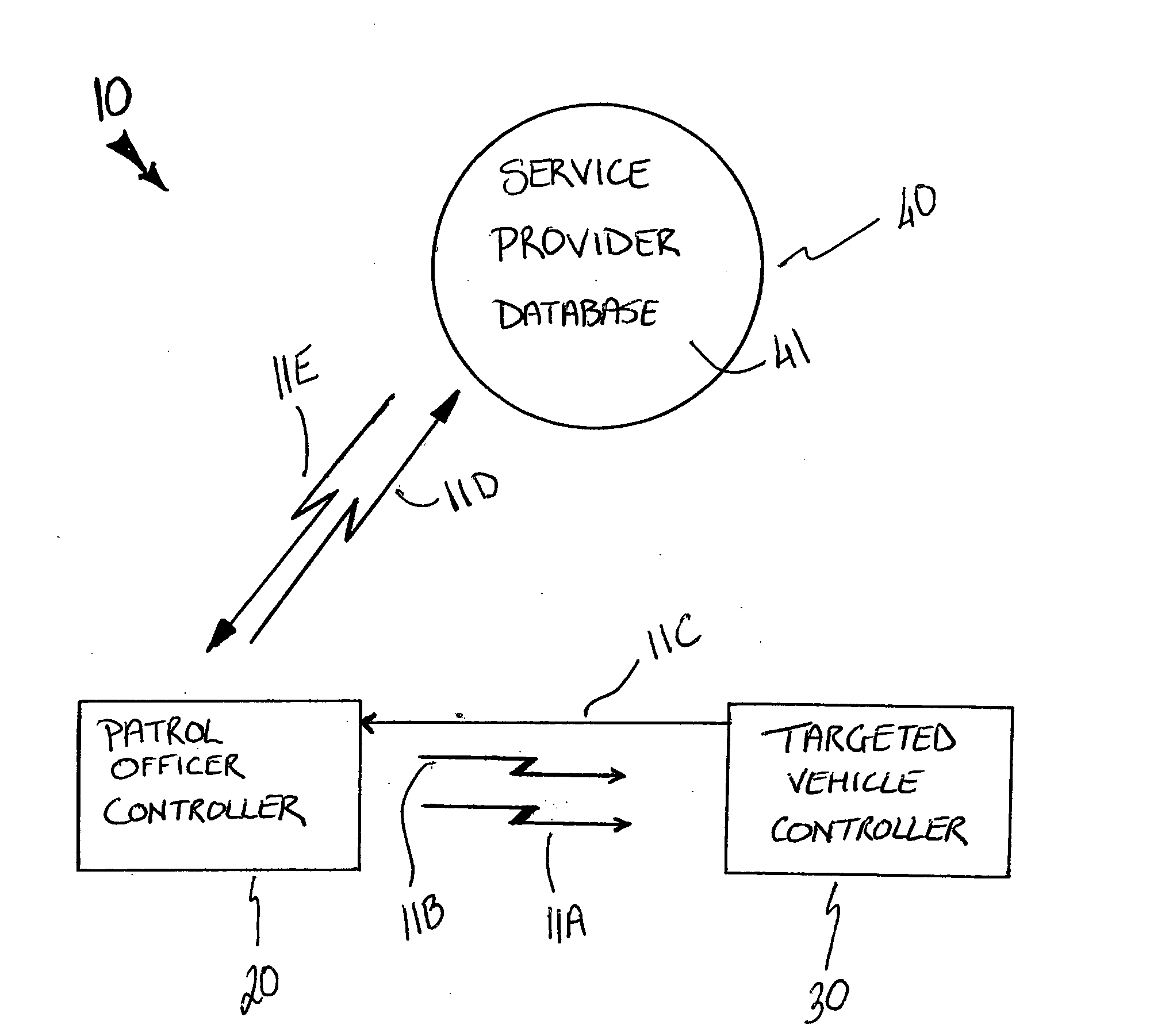
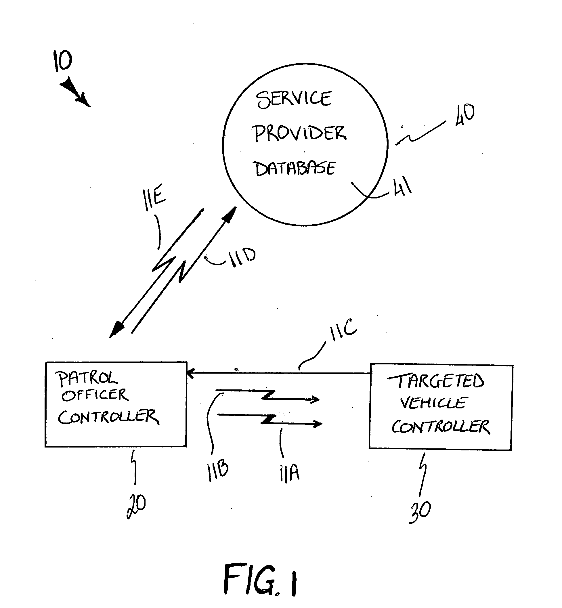
[0012] The vehicle control system includes a first controller housed within a law enforcement vehicle. Such a first controller includes a wireless mechanism for determining a vehicle identification number unique to the targeted vehicle when the targeted vehicle enters a predetermined proximity surrounding the first controller. The wireless mechanism generates and transmits a short range inquiry signal to the targeted vehicle for effectively requesting the vehicle identification number.
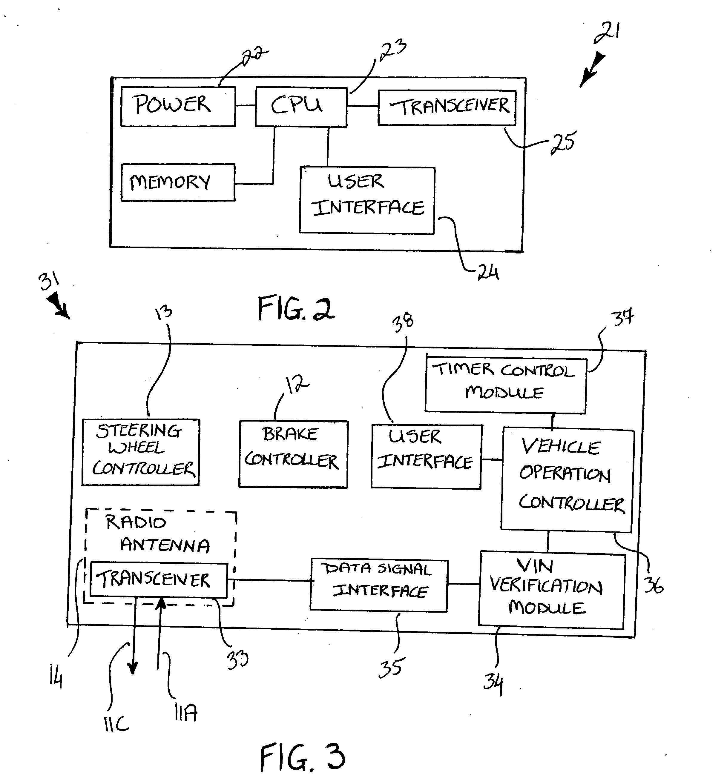
[0014] A second controller is housed within the targeted vehicle. Such a second controller includes a wireless mechanism for effectively communicating with the first controller and further includes a mechanism for controlling a velocity of the targeted vehicle advantageously without restricting braking and steering capabilities of the targeted vehicle so that a driver of the targeted vehicle can safely maneuver the targeted vehicle to an area remote to oncoming traffic.
[0015] The second controller wireless mechanism preferably includes a transceiver embedded within an antenna system of the targeted vehicle, a vehicle identification module housed within the second controller, and a data signal interface for communicating the inquiry and deactivation signals to the vehicle identification module. Such a second controller wireless mechanism preferably further includes a vehicle operations controller electrically mated to the vehicle identification module and a timer control module operably connected to the vehicle operations controller. The timer control module is responsive to a control signal transmitted by the vehicle operations controller for advantageously and effectively inhibiting a driver of the targeted vehicle from accelerating after the deactivation signal has been received by the second controller. A user interface may be electrically mated to the vehicle operations controller for allowing the driver to manually override the deactivation signal during emergency situations.
[0019] During operating conditions, the second controller generates and sends the response signal to the first controller, and the first controller generates and transmits the request signal over the dedicated communications link to the service provider after receiving the response signal from the second controller. Such a service provider subsequently generates an authorization signal based upon the request signal and transmits the authorization signal over the dedicated communication link such that the law enforcement officer can advantageously quickly and efficiently obtain the authorization code during a fast-speed pursuit. Finally, the first controller wirelessly transmits the deactivation signal to the targeted vehicle for effectively causing the second controller to disable selected operating characteristics of the targeted vehicle in such a manner that the targeted vehicle can advantageously be quickly and safely subdued by the law enforcement officer.

Problems solved by technology

The frustration with the consequences of dangerous high speed chases, many of which result in serious injuries, and often to innocent bystanders, has even engendered the use of a system commonly known as “stop sticks” that requires the police to get in front of the chased vehicle and place a line of spikes in its path.
As a result, law enforcement officials may need to terminate chase efforts because of danger to third parties and thus, permit criminals to escape apprehension.
When such termination is not a viable choice, however, risks continue to accrue until the course of the chase is resolved.
However, even though the police have stopped a vehicle they are still subject to the serious risk that the operator can speed off again, often running them down or even shooting the officer, and escaping.
The timely use of such a system quickly terminates street and highway chases before they escalate into dangerous high-speed situations.

Method used


Image

  • Remotely operable vehicle disabling system
  • Remotely operable vehicle disabling system
  • Remotely operable vehicle disabling system

Examples


Embodiment Construction

[0028] The present invention will now be described more fully hereinafter with reference to the accompanying drawings, in which a preferred embodiment of the invention is shown. This invention may, however, be embodied in many different forms and should not be construed as limited to the embodiment set forth herein. Rather, this embodiment is provided so that this application will be thorough and complete, and will fully convey the true scope of the invention to those skilled in the art. Like numbers refer to like elements throughout the figures.

[0029] The system of this invention is referred to generally in FIGS. 1-7 by the reference numeral 10 and is intended to provide a remotely operable vehicle disabling system. It should be understood that the system 10 may be used to disable many different types of vehicles, such as motorcycles and semi-trucks, and should not be limited in use to only motor vehicles.

[0030] Referring initially to FIGS. 1 and 2, the system 10 includes a first...


PUM


Abstract

A vehicle control system includes a first controller including a wireless mechanism for determining a vehicle identification number. A second controller includes wireless mechanisms for communicating with the first controller and for controlling a velocity of the targeted vehicle without restricting the braking and steering capabilities thereof. The system includes a service provider including a database containing authorization codes unique to vehicle identification numbers. A communications link transmits confidential data streams to the service provider. The communications link includes a wireless cellular telephone network. The system includes a request signal, an authorization signal, and a deactivation signal. The second controller sends the response signal to the first controller, which transmits the request signal to the service provider. An authorization signal is transmitted to the law enforcement officer. The first controller transmits the deactivation signal to the vehicle, causing the second controller to disable selected operating characteristics thereof.

Description

CROSS REFERENCE TO RELATED APPLICATIONS [0001] Not Applicable. STATEMENT REGARDING FEDERALLY SPONSORED RESEARCH OR DEVELOPMENT [0002] Not Applicable. REFERENCE TO A MICROFICHE APPENDIX [0003] Not Applicable. BACKGROUND OF THE INVENTION [0004] 1. Technical Field [0005] This invention relates to vehicle disabling systems and, more particularly, to a remotely operable vehicle disabling system for allowing law enforcement personnel to remotely disable a targeted vehicle. [0006] 2. Prior Art [0007] The problem of reducing high-speed chases often associated with pursuing a traffic violator, a drunk driver, or a stolen vehicle, has received great attention within recent years and by numerous and widely varied approaches. The frustration with the consequences of dangerous high speed chases, many of which result in serious injuries, and often to innocent bystanders, has even engendered the use of a system commonly known as “stop sticks” that requires the police to get in front of the chased ...

Claims


Application Information

Patent Timeline
IPC IPC(8): G05D1/00G08C19/00
CPCG08C2201/42G08C17/02
Inventor PUAMAU, SOANE R.
Owner PUAMAU SOANE R
Learn More