In-core fuel restraint assembly

a fuel assembly and restraint technology, applied in the field of fuel assemblies, can solve the problems of high amount of column bowing of fuel elements, damage to fuel assembly elements, and partial control rod insertion, so as to improve the resistance to lifting and vibration, reduce harmful compressive forces, and superior restraint of fuel assembly

Inactive Publication Date: 2006-11-09
WESTINGHOUSE ELECTRIC CORP
View PDF20 Cites 52 Cited by
  • Summary
  • Abstract
  • Description
  • Claims
  • Application Information

AI Technical Summary

Benefits of technology

[0014] These needs and others are satisfied by the present invention, which is directed to an in-core fuel restraint assembly which replaces conventional compressive coil and cantilever-type spring restraining devices with a combination of restraint elements which provide superior restraint of the fuel assembly, improving resistance to lift

Problems solved by technology

To be effective, the clamping forces provided by the aforementioned compressive springs, whether of the cantilever or the coil variety, must be substantial and can, therefore, result in damage to elements of the fuel assembly 2.
The axially compressive nature of the spring force frequently causes an undesirably high amount of column bowing of the fuel elements (e.g., fuel rods 12 and guide thimbles 8).
Column bowing can result in disadvantages such as, for example, partial control rod insertion and slower scram times. Scram is a term which has evolved in the nuclear art to be commonly used when referring to an emergency shutdown of a nuclear reactor.
However, the disclosed spring combination does not address axial compression of the entire fuel assembly in order to provide vertical restraint, without causing undesirable bowing of the fuel elements between the upper and lower core plates.
However, in addition to gene

Method used


Image

  • In-core fuel restraint assembly
  • In-core fuel restraint assembly
  • In-core fuel restraint assembly

Examples


example

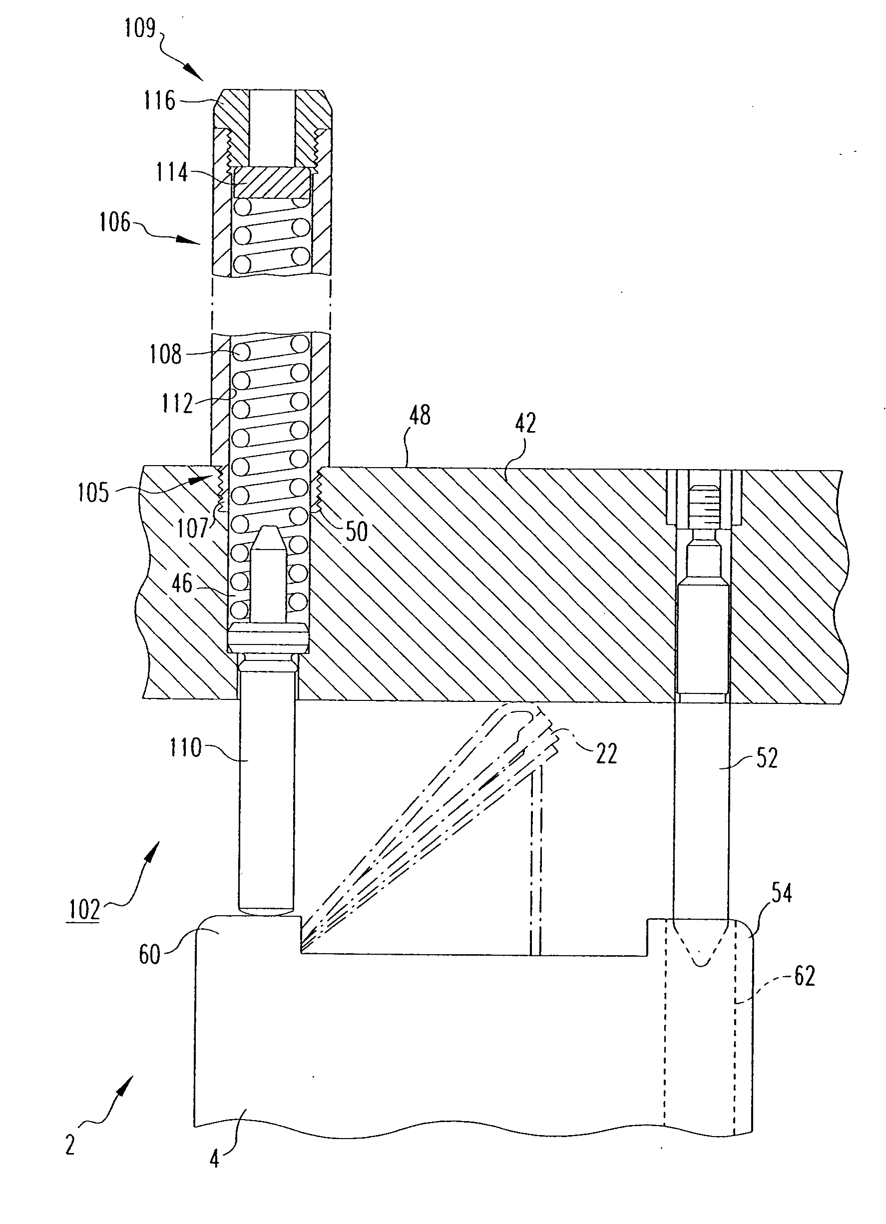
[0039] By way of a representative example, which will be used for illustrative purposes herein throughout, and which is not limiting upon the scope of the invention, Westinghouse Electrical Company LLC has a known core design which is commercially available under the designation AP-1000. Westinghouse Electric Company LLC has a place of business in Monroeville, Pa. The AP-1000 design includes 157 fuel assemblies 2. Therefore, in accordance with the aforementioned restraint assembly 100 of the invention, two spring packs 102 would be employed at each fuel assembly 2 location in the core 30, for a total of 314 spring packs 102.

[0040] As previously discussed, the push rod 110 of each spring pack 102 engages and provides a compressive force at a corner (see, for example, corner 60 of fuel assembly top nozzle 4 of FIG. 3) of the fuel assembly top nozzle 4. More specifically, as shown in FIG. 3, in the AP-1000 Example, the push rod 110 of spring pack 102 engages corner 60 of the top nozzl...


PUM


Abstract

An in-core restraint assembly is for a nuclear reactor core including an upper core plate, a lower core support plate and a plurality of fuel assemblies extending longitudinally therebetween. Each fuel assembly includes top and bottom nozzles and a plurality of elongated fuel rods extending therebetween. The in-core restraint assembly includes a first restraint element, such as a spring pack, coupled to the upper core support plate and providing a substantially axial compressive force on the top nozzle of the fuel assembly. An optional second restraint element is structured to be coupled to the lower core plate in order to engage and further restrain the fuel assembly proximate the bottom nozzle. The second restraint element includes a pin member extending from the bottom nozzle of the fuel assembly and received in a socket coupled to the lower core support plate, whereby this mating sustains a longitudinal (vertical) frictional force which must be overcome before fuel assembly lift off can occur.

Description

BACKGROUND OF THE INVENTION [0001] 1. Field of the Invention [0002] The present invention relates generally to fuel assemblies for a nuclear reactor core and, more particularly, to an in-core restraint assembly for securing the fuel assemblies between upper and lower core plates. [0003] 2. Background Information [0004] The reactor core within a typical commercial nuclear power reactor is formed by numerous elongated fuel assemblies arranged in a cylindrical vessel. [0005] As shown in FIG. 1, each fuel assembly 2 generally includes top and bottom nozzles 4,6 with a plurality of transversally spaced guide thimbles 8 extending longitudinally between the nozzles 4,6, a number of transverse support grids 10 axially spaced along and attached to the guide thimbles 8, an organized array of elongated fuel rods 12 transversely spaced and supported by the support grids 10, and a centrally located instrument tube 14. The top and bottom nozzles 4,6 have end plates (not shown) with flow openings ...

Claims


Application Information

Patent Timeline
IPC IPC(8): G21C15/00
CPCG21C3/3305G21C3/331G21C3/3315Y02E30/40G21Y2002/303G21Y2002/601G21Y2004/30G21Y2002/201Y02E30/30
Inventor BALOG, LEONARD J.
Owner WESTINGHOUSE ELECTRIC CORP
Why Eureka
Try Eureka