[0015] It is an object of the present invention to provide a construction bracket that provides a more efficient way of connecting roof rafters by decreasing framing time and reducing the number of angle cuts required to fabricate sloped roofs. It is another object of the present invention is to provide a construction bracket that eliminates the need for compound angle cuts on rafter ends for roof hips and valleys. It is still another object of the present invention to provide a construction bracket that allows for easier attachment of light framing to large structural members at angled building configurations. It is a further object of the present invention to provide an internal ducting
system for venting a roof that is more aesthetic than external systems and does not increase the height of the ridge. It is yet a further object of the present invention to provide improved
airflow in a ventilated roof, even roofs with multiple gables, hips and / or valleys. It is another object of the present invention to provide proper roof ventilation even when the roof is covered with
snow.
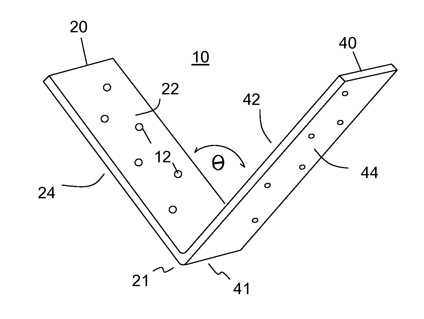
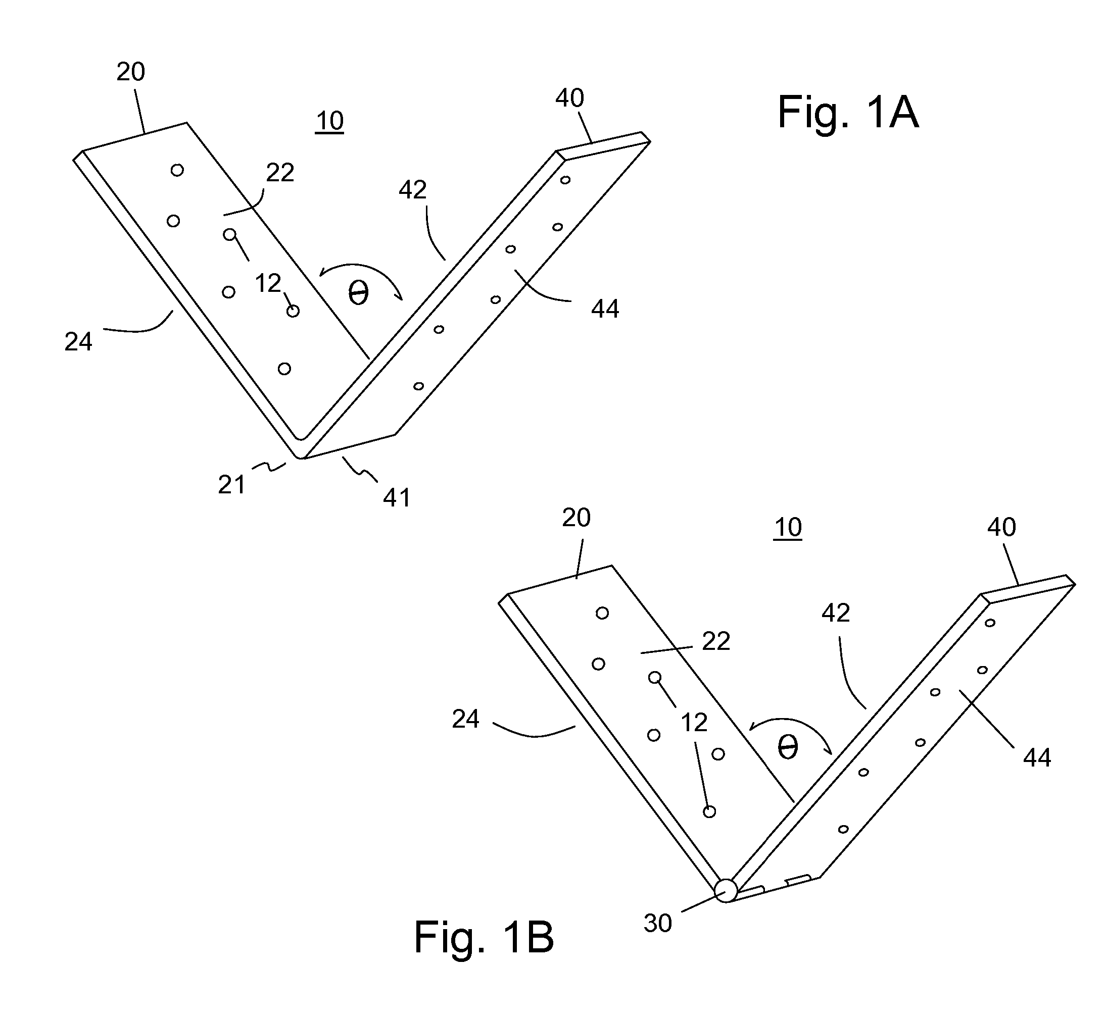
[0016] The present invention achieves these and other objectives by providing a construction bracket that has at least a first flange and a second flange connected to each other along one edge of each flange forming a “V” shaped bracket, which is either at a fixed or an adjustable angle. In its simplest configuration, the first flange is configured to connect to the end of a roof rafter that is square
cut. An end having a square cut is one whose end is substantially perpendicular to the length of the board. The second flange is configured to connect to the end of a second roof rafter that is the opposing rafter to the one attached to the first flange, or in the case of a shed roof, to a header board. Because the need to make angled or compound angle cuts to the ends of the rafters forming the roof structure is eliminated, the time required to frame a roof is decreased thus providing a savings on labor cost.
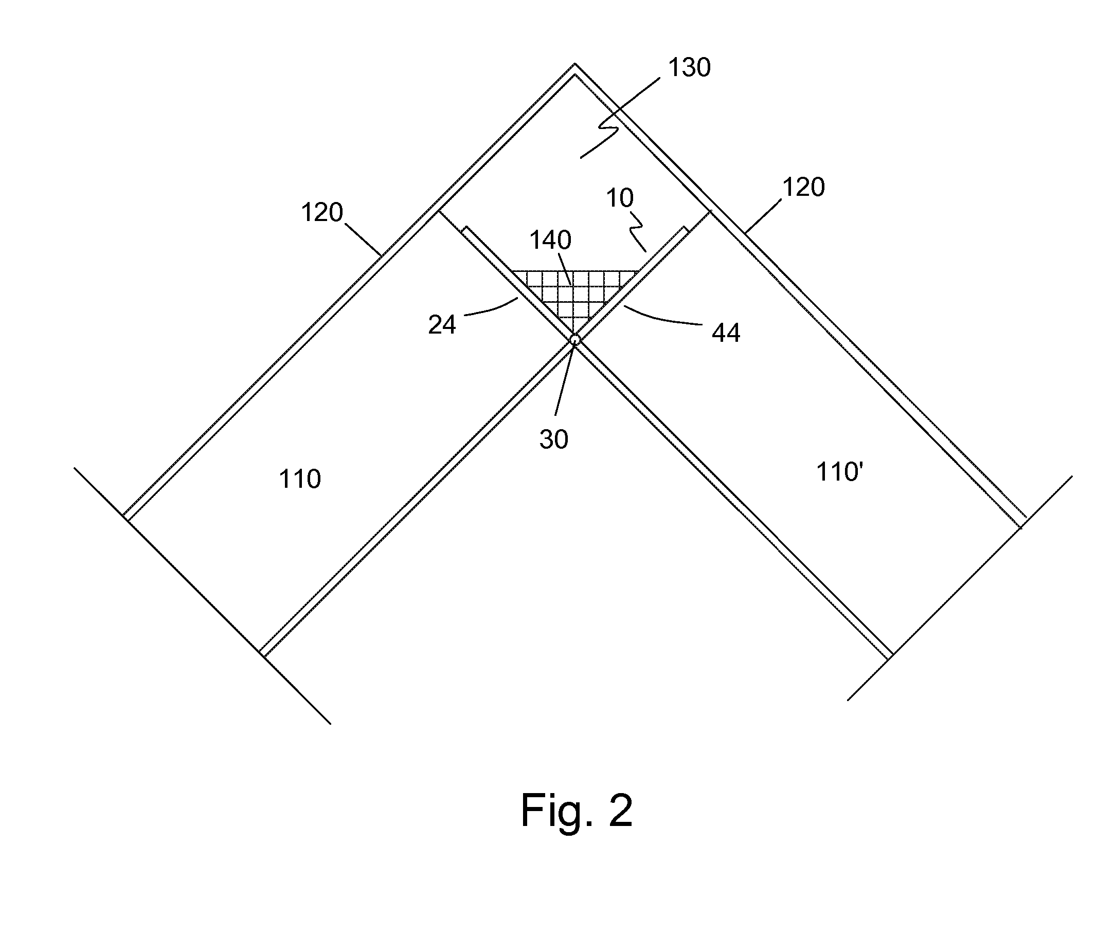
[0017] Using a construction bracket of the present invention to join each paired rafter, or a shed roof rafter to a header board, creates a continuous internal space at the ridge, hip, or valley of a roof bounded by a covering such as the roof sheathing, which is typically plywood, or at the junction of the rafters of a shed roof with the header wall bounded by the shed roof sheathing. Unlike the typical construction structure where a ridge board, hip board or valley board is used to facilitate connecting the paired rafters together and creating a
solid junction with the sheathing along these structures, this feature of the present invention, i.e. creating a continuous internal space along the rafter / rafter junctions, allows for improved
airflow and roof ventilation even when the roof is covered by snow or when a large number of gables, ridges, hips, and valleys are present. This is so because no ridge vent is required.
Gable end vents provide the vent outlet for the internal space. It also allows for improved
airflow of shed roofs. An added feature is the improved aesthetic look of the roof line. Even in long, extended roof ridges, cupolas may be used to vent the roof at predetermined locations. The use of cupolas is an aesthetically pleasing and acceptable roof design feature.
[0019] In addition to the use of rafter joining boards, standard joist brackets may also be used to attach to the rafter joining boards to further facilitate the rafter construction /
assembly process. In another embodiment, the construction bracket may have joist hangers attached directly to each of the first and second flanges or may be integrally formed with the construction bracket. In yet another embodiment of the present invention, the construction bracket may have a predetermined, continuous length capable of receiving a predetermined number of rafters. An
advantage of this embodiment having a pivotable junction allows the framers to attach a predetermined number of rafters to the construction bracket and then raise this “pre-built” section of roof framing to the desired location. Markings may also be incorporated onto the surface of each flange at locations that match the proper construction code-defined spacing between each rafter to eliminate the need to measure, mark, and attach each rafter according to the required construction code spacing. This has the
advantage of also saving time during the framing process.
[0020] For roofs of relatively low
pitch, another embodiment of the present invention provides a way to insure that a sufficient internal space is formed between the rafters. In this embodiment, the construction bracket includes a base between the first and second flanges. In use, this embodiment has the shape of square-shaped “U” where the extending legs
flare away from the inside of the “U”. The base, which corresponds to the bottom of the square-shaped “U”, provides the necessary spacing between the first and second flanges to create a sufficient internal volume between the rafters. Like the V-shaped construction bracket of the present invention, the first and second flanges may be fixedly attached to each side of the base or they may be pivotably attached allowing for a range of roof pitches.
[0021] The U-shaped bracket of the present invention may also have the additional features that the V-shaped bracket may have as described above. Both the U-shaped and V-shaped brackets may incorporate a predetermined amount of insulation at the bottoms of the brackets to further reduce possible heat loss through the bracket. The U-shaped bracket may be further configured to accommodate a ridge beam against the outside surface of the base.

