
Stablized guided conveyor belt with multiple base chains and interchangeable conveyor plates

a conveyor belt and guide technology, applied in the direction of conveyors, transportation and packaging, etc., can solve the problems of high cost of failure, and lug disengagement, and achieve the effect of convenient detachment from the transport chain, preventing buckling and rippling of the conveyor belt, and easy attachment independently

Inactive Publication Date: 2006-11-16
MEADWESTVACO PACKAGING SYST LLC
View PDF14 Cites 8 Cited by
  • Summary
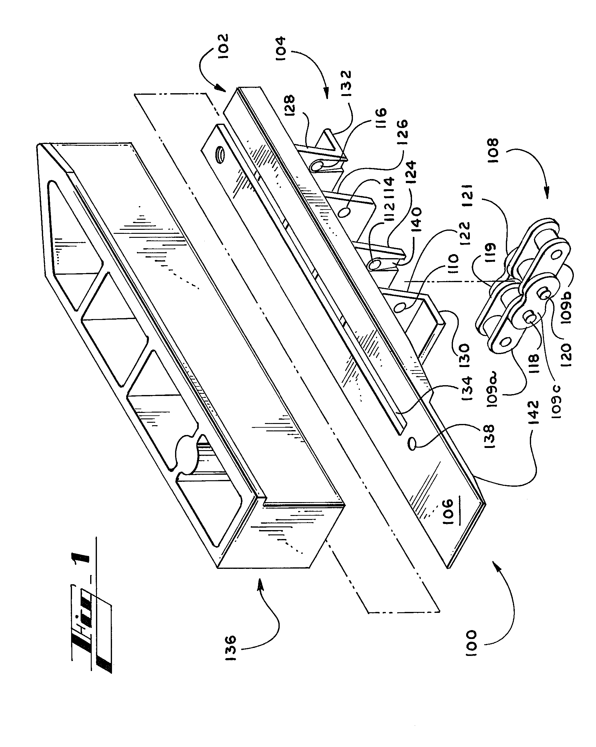
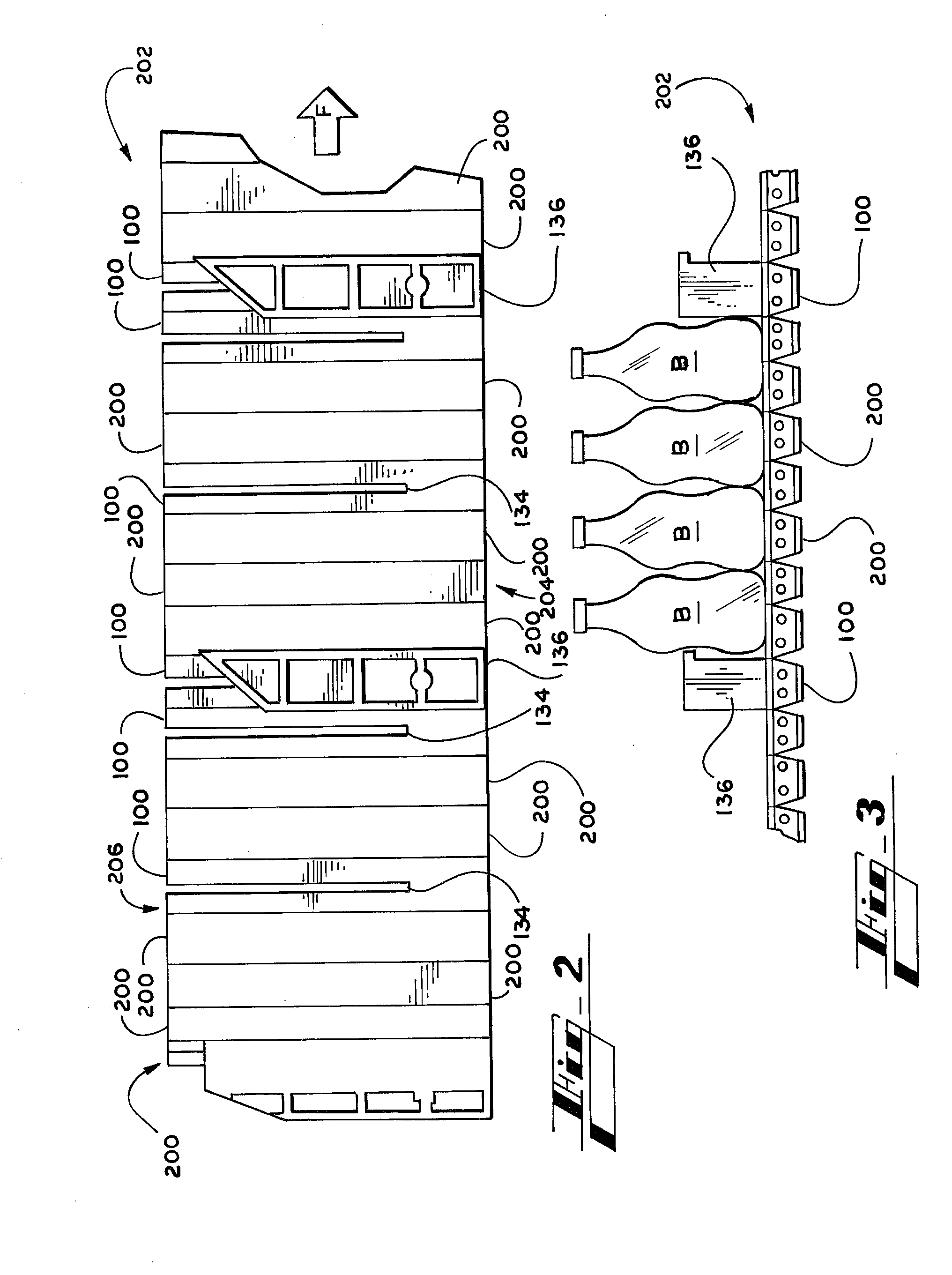
  • Abstract
  • Description
  • Claims
  • Application Information

AI Technical Summary

Benefits of technology

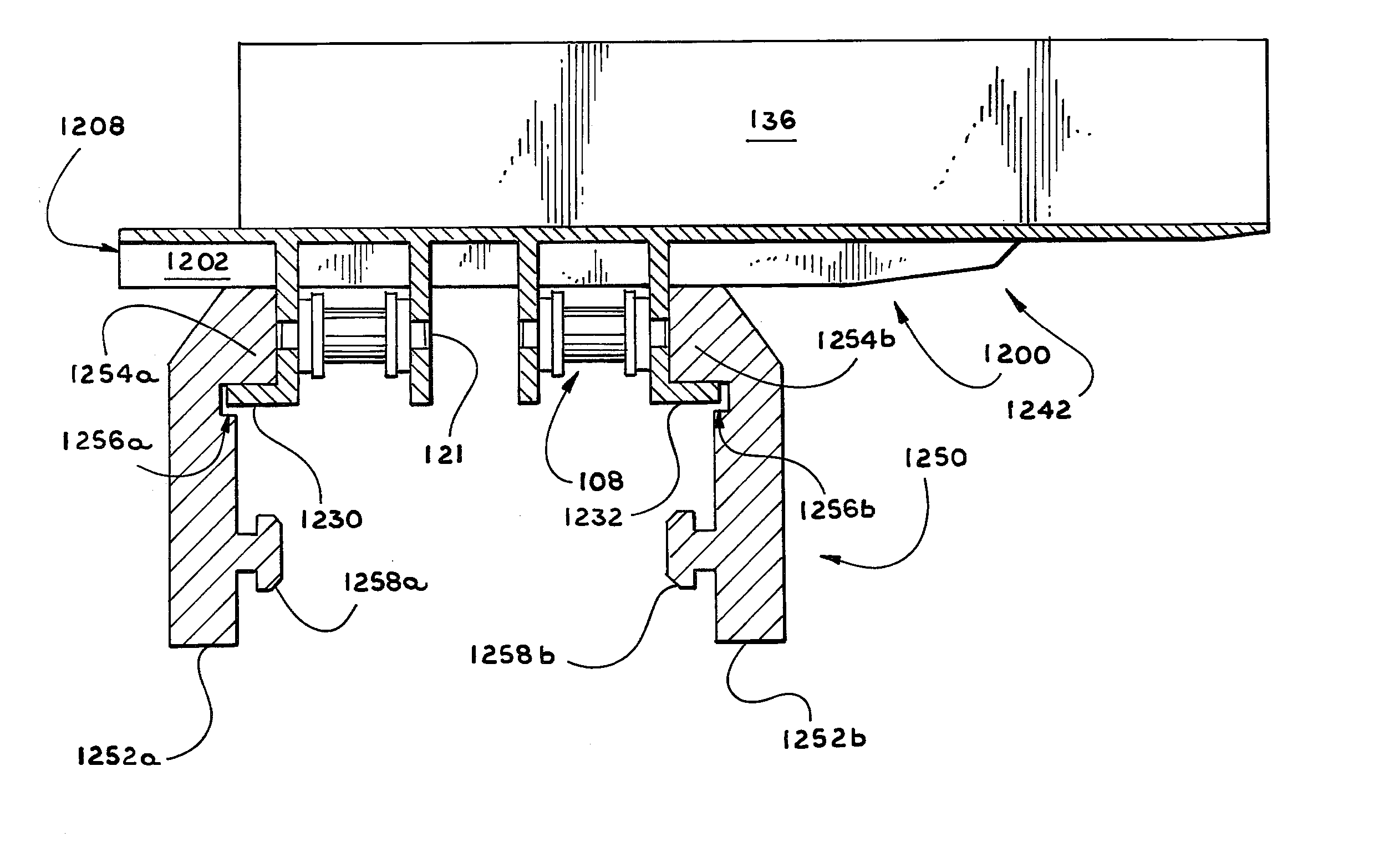
[0007] The various embodiments of the present invention address the shortcomings in the prior art by providing a guided conveyor belt that is driven by a transport chain that utilizes dual steel base chains. The improved conveyor belt offers a smooth, substantially flat surface for conveying articles. Generally described, the surface of the conveyor belt is formed from multiple conveyor plates that can be easily attached independently of one another in a side by side fashion onto the transport chain and are readily detachable from the transport chain for replacement, repair, or reordering. The plates function selectively as a platform on which to mount accessories such as lugs and include means for receiving accessories and for locking accessories into place. The conveyor belt is guided and supported by a smooth rail. Both the belt and the rail include interacting stabilizing features that cooperate to prevent buckling and rippling of the conveyor belt, which also reduces stretching and other damage to the transport chain.
[0008] More specifically, each plate is preferably preformed of a somewhat elastically deformable material such as a plastic or other polymer. In the exemplary embodiments, plastic is injection molded to form the unitary structure of each plate, although any suitable means of manufacture that yields the structural and functional elements described herein will serve the objects of the invention. Suitable means of manufacture include, for example, alternative methods for manufacturing unitary plates such as thermoforming, pressure forming, low pressure foam molding, and vacuum forming. In alternative embodiments, the plate is formed from several components that may be different materials. For example, at least the upper surface of each plate may be formed from steel with the remainder of the plate being plastic. Accordingly, suitable means for manufacture also include twin sheeting or other methods for manufacturing and assembling plate structures formed from several components which are secured together using securing means such as adhesives and welds. A unitary structure is preferred in certain applications, however, to drastically reduce the cost of the plate and to increase part consistency.
[0013] The stabilizing means includes a guide extending at an angle from both the inside tab and the outside tab. The guides extend outward toward the end edges of the plate so as to engage the edge of a flange extending from the rail. The guides prevent buckling and tilting of the belt along its length and width by restricting back and forth and side to side motion by further limiting the moment of the mounting plate even when the lug experiences cantilevered forces.
[0014] The use of multiple base chains is an important aspect of the invention, increasing the effectiveness of the support and stabilization features of the conveyor belt and rail. More specifically, the dual base chains of the exemplary embodiments are spaced apart, allowing the guides, outermost tabs, and sides of the rail to be spaced further apart, thereby decreasing the impact of moments and other forces caused by cantilevered loads on the conveyor surface. Each plate is stabilized indirectly against the moment about its transverse axis, which is parallel to the direction of machine flow, that tends to cause the belt to twist along its length. Further, each plate is stabilized directly against the moment about its longitudinal axis, which is perpendicular to the direction of travel, that tends to cause the belt to buckle. Thus, excessive and uneven wear and drag on the tabs, guides, and hinge pins is prevented, as is instability of the conveyor belt surface.
[0015] According to still another aspect of the invention, a portion of the underside or bottom surface of the body of each plate is substantially thinner and tapers in the direction of the outside edge of the conveyor belt. The slope of the bottom surface of the tapered portion defines an acute angle relative to the top surface of the tapered portion. The taper may be gradual or stepped. This tapering maximizes the thickness and strength of the nontapered portion of the conveyor belt, while providing a ledge over which articles slide into a carton and under which end flaps of cartons can pass. The tapered portion is flexible enough to maintain a degree of pressure on the carton flap below, where the pressure is generated by the articles resting on the upward facing surface of the tapered portion. In alternative embodiments, the taper is abrupt such that the tapered portion has a relatively uniform thickness, which is substantially less than the thickness of the rest of the body of the plate. Thus, as used herein, the word taper is expansively defined as to make thinner or narrower at one end or at both ends.
[0018] The plates are attached to the transport chain independently of one another, such that the plates are not interlocked. Rather, the links of the base chains are interlocked preferably via the hinge pins, and the plates are then attached to the hinge pins. Independent attachment facilitates detaching and reordering of the plates to accommodate various grouping arrangements, carton sizes, packaging speeds, and other demands of the particular application in which the plates are used.

Problems solved by technology

This problem is exacerbated when accessories such as lugs are mounted to the plates to facilitate grouping or metering of articles.
The pins concentrate the reaction loads in singular areas of the plastic chain top, and thus, have the tendency to snap causing the lug to disengage.
Such failures are costly, as the affected plate must be replaced or the broken screw or pins removed to mount another lug.
This approach disadvantageously exposes the transport chain to increased wear and to elongation over time, particularly, as the transport chains are commonly constructed using links formed from plastic that are interlocked with steel pins.
Such single chain arrangements provide little resistance to rotational forces, and are more susceptible to stretching and other damage that can be caused by such forces as well as by typical operating conditions.

Method used


Image

  • Stablized guided conveyor belt with multiple base chains and interchangeable conveyor plates
  • Stablized guided conveyor belt with multiple base chains and interchangeable conveyor plates
  • Stablized guided conveyor belt with multiple base chains and interchangeable conveyor plates

Examples


Embodiment Construction

[0033] As required, detailed embodiments of the present invention are disclosed herein. It will be understood that the disclosed embodiments are merely examples to illustrate aspects of the invention that may be embodied in various and alternative forms. The figures are not necessarily to scale, and some features may be exaggerated or minimized to show details of particular components. In other instances, well-known materials or methods have not been described in detail to avoid obscuring the present invention. Therefore, specific structural and functional details disclosed herein are not to be interpreted as limiting, but as a basis for the claims and for teaching one skilled in the art to variously employ the present invention.

[0034] Referring now to the drawings in which like numerals indicate like elements throughout the several views, the drawings illustrate certain of the various aspects of exemplary embodiments of a stabilized conveyor belt with a guided transport chain and ...


PUM


Abstract

A stabilized and guided conveyor belt (202) includes multiple transport chains (108) and interchangeable conveyor plates (100) that form the surface of the conveyor belt (202). The conveyor plates (100) can be easily attached independently of one another in a side by side fashion onto the transport chains (108) and are readily detachable from the transport chains (108) to facilitate replacement or rearrangement. Certain of the plates (100) function selectively as a platform on which to mount accessories such as lug members (136) and include means for receiving (134) accessories and for locking (138) accessories into place. The conveyor belt (202) is guided and supported by a smooth rail (420). Both the plate (100) and the rail (420) include interacting stabilizing features (130, 132, 424a, 424b) that cooperate to prevent buckling and rippling of the transport chain (108).

Description

CROSS REFERENCE TO RELATED APPLICATIONS [0001] This application claims priority to U.S. application Ser. No. 60 / 676,458, filed Apr. 29, 2005, the entirety of which is incorporated herein by reference.TECHNICAL FIELD [0002] The invention relates to a conveying apparatus, and more particularly, to a stabilized and guided conveyor belt with multiple base chains and interchangeable conveyor plates. BACKGROUND OF THE INVENTION [0003] Articulated roller chain conveyors are commonly used in packaging applications to convey articles such as bottles or cans through a packaging machine to be loaded into paperboard cartons. It is often the practice to attach plates to the roller chain or to interlock plates to provide a smooth surface upon which the articles and / or cartons are conveyed. It is important to prevent the conveyor surface from tilting, buckling, or excessively undulating, which topples articles, interferes with other packaging machine components such as lane dividers, damages carto...

Claims


Application Information

Patent Timeline
Patent Type & Authority Applications(United States)
IPC IPC(8): B65G17/38
CPCB65G17/123B65G17/44B65G17/34B65G17/14
Inventor CASH, JOHNW IIIFLAGG, MICHAEL F.CHUBA, LARRY D.
Owner MEADWESTVACO PACKAGING SYST LLC
Learn More