Filter

a filter and filter material technology, applied in the field of filters, can solve the problems of adsorption of contaminants by the filtering material, pressure drop, and gradual fall of hydraulic conductivity of traditional filters, and achieve the effect of reducing the number of contaminants, and improving the quality of the filter

Inactive Publication Date: 2006-11-16
DMA SORPTION
View PDF8 Cites 18 Cited by
  • Summary
  • Abstract
  • Description
  • Claims
  • Application Information

AI Technical Summary

Benefits of technology

[0026] The present invention relates to a filter with layers of filtration medium optionally also with layers of spacer medium and bypass spaces at the edges of the layers of filtration medium and of the spacer medium if any. The invention also rel

Problems solved by technology

Traditional filters suffer from the dilemma that on one hand they need to have an open structure in order to retain a certain hydraulic conductivity, but on the other hand the structure must not be too open in order to retain dispersed particles and compounds.
Traditional filters also suffer from gradually falling hydraulic conductivity (pressure drop) as more and more particles are trapped within the filtration medium.
When the contaminated liquid passes through the filter in the spacer media, some contaminants are adsorbed by the filtering material.
The drawbacks of these filters are that although the filter capacity is increased, there is stil

Method used


Image

  • Filter
  • Filter
  • Filter

Examples


example 1

[0282] The hydrophobic cellulose fibres are made hydrophobic by the following process:

[0283] The cellulose fibre sheet is dipped in a solution of 5-50% hydrophobic emulsion (e.g. 200 G resin emulsion per litre water=20%) for about ½-5 minutes. By passing the sheet through a roll, the water is pressed out of the cellulose sheet. Hereafter the sheet is dipped in a 1-30% solution of potassium / sodium sulphate (e.g. 20 G alum per litre water=2%) for about ½-5 minutes. After pressing out the water of the cellulose sheet by a roll, the process is followed by a drying process in an oven (110 degree C. / 20 minutes).

example 2

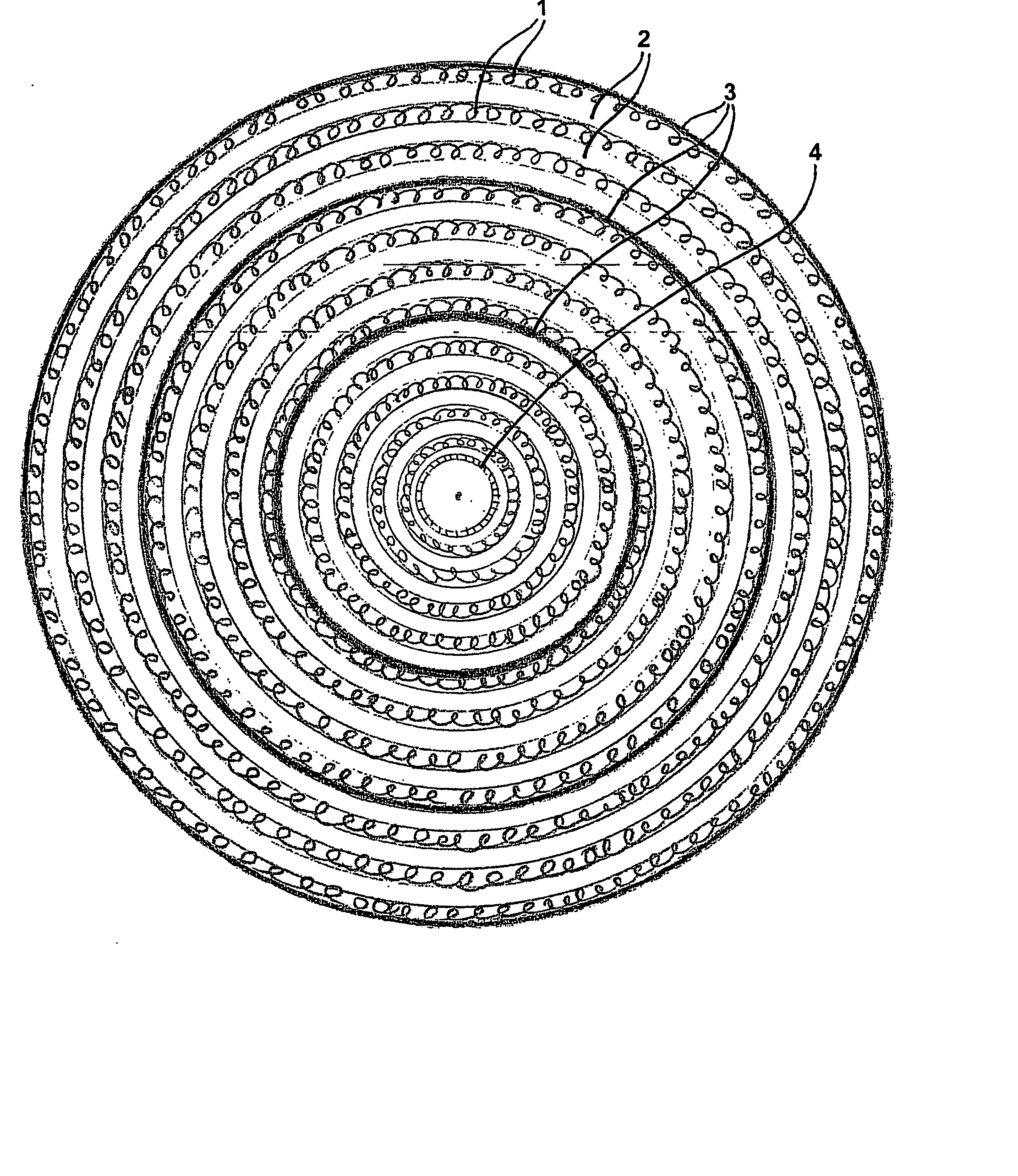
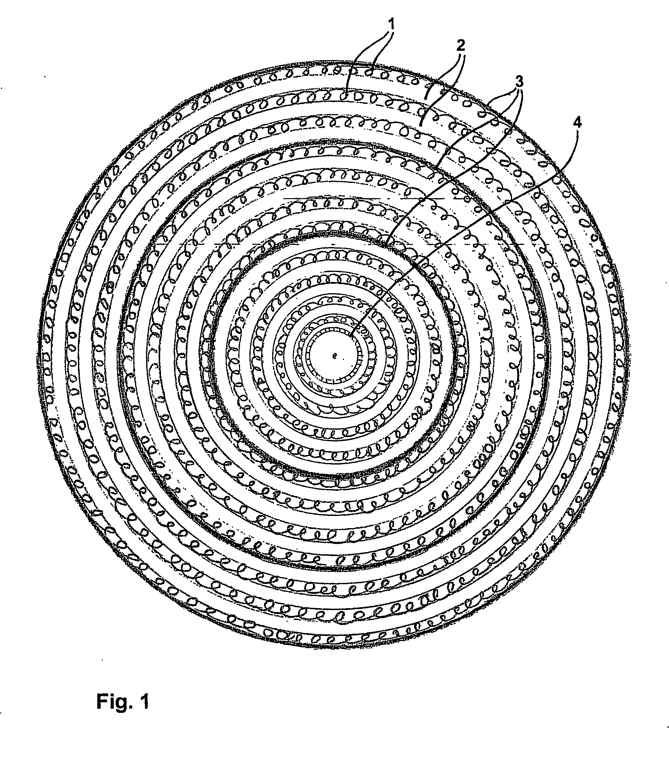
[0284] A filter cartridge (test cartridge 1) utilising spacer medium and filtration medium according to the present disclosure but without the inner zone, mounted with annular end caps bonded totally to the ends of the filter, exhibits a filter life approximately two times greater than a control filter cartridge (control filter cartridge) wrapped with only filtration medium.

[0285] Visual inspection and dissection of the filter cartridge (test cartridge 1) shows a contaminant loading corresponding to a radial flow from the outermost layer to the central coil covering about 10-15% of the filter. In comparison only the outermost layer of filtration medium displayed contaminant loading in control filter (control filter cartridge), covering about 2-5% of the filter.

example 3

[0286] A filter cartridge (test cartridge 2) utilising only filtration medium, mounted with annular end caps with two circle packing, this filter exhibits a filter life 1½ times better than a control cartridge (control filter cartridge) having end caps totally bonded to the ends of the filter.

[0287] Visual inspection and dissection of the filter cartridge shows a contaminant loading corresponding to a radial flow from the outermost layer to the central coil covering about 25% of the filter.


PUM

PropertyMeasurementUnit
Flow rateaaaaaaaaaa
Areaaaaaaaaaaa
Dimensionaaaaaaaaaa

Abstract

The present invention relates to a filter for liquid filtration, the construction of the filter ensure increased filtration capacity by using up the filtration medium rather that clogging up. The filter comprises layers of filtration medium (2) and optionally also layers of spacer medium (1). Liquid to be filtered can through bypass spaces circumvent a number of layers of filtration and/or spacer medium and is by at least one sealing (3) directed through the filtering area of filtration medium. End caps (5) with perforations (6) allow the liquid to be distributed within the bypass space between the edges of the layers of filtration medium and spacer medium. Rolled filters with a central core (4) to drain off the filtered liquid can be constructed in large dimensions. Also disclosed is a method making the filter. The filters are suitable for many purposes, especially for filtering liquid with oil.

Description

FIELD OF INVENTION [0001] The present invention relates to a filter, a method of making a filter and a method of filtering a contaminated fluid. The invention particularly relates to a filter having a composition by which the filter is not clogged up due to deposit of contaminants within outer part of filtering media. All patent and non-patent references cited in the present application, are hereby incorporated by reference in their entirety. BACKGROUND OF INVENTION [0002] Filters for removing contaminating components from liquid are known from the prior art. Filters are usually constructed to draw the fluid across one or more layers of a porous medium, hereby separating dispersed particles or compounds from a dispersing fluid. [0003] Traditional filters suffer from the dilemma that on one hand they need to have an open structure in order to retain a certain hydraulic conductivity, but on the other hand the structure must not be too open in order to retain dispersed particles and co...

Claims


Application Information

Patent Timeline
IPC IPC(8): B01D29/00B01D25/00B01D29/15
CPCB01D25/001B01D29/15B01D2201/291B01D2201/34B01D25/24B01D29/54B01D29/58
Inventor OLSEN, OLELARSEN, LISE NOHR
Owner DMA SORPTION
Why Eureka
Try Eureka