
Methods and apparatus for remote temperature measurement of a specular surface

a technology of specular surface and temperature measurement, which is applied in the direction of heat measurement, optical radiation measurement, instruments, etc., can solve the problems of insufficient accuracy, measurable and undesirable difference in sheet resistance, and sensitive to the peak temperature produced on the substrate surfa

Inactive Publication Date: 2006-11-16
ULTRATECH INT INC
View PDF20 Cites 16 Cited by
  • Summary
  • Abstract
  • Description
  • Claims
  • Application Information

AI Technical Summary

Problems solved by technology

While the LTP process is quick and effective, the results are sensitive to the peak temperature produced on the substrate surface.
A difference in the peak annealing temperature of as little as a 5° C. can result in a measurable and undesirable difference in sheet resistance.
Unfortunately, this approach is relatively complex and not sufficiently accurate for the range of temperatures and the variations in surface emissivity associated with LTP.

Method used


Image

  • Methods and apparatus for remote temperature measurement of a specular surface
  • Methods and apparatus for remote temperature measurement of a specular surface
  • Methods and apparatus for remote temperature measurement of a specular surface

Examples


Embodiment Construction

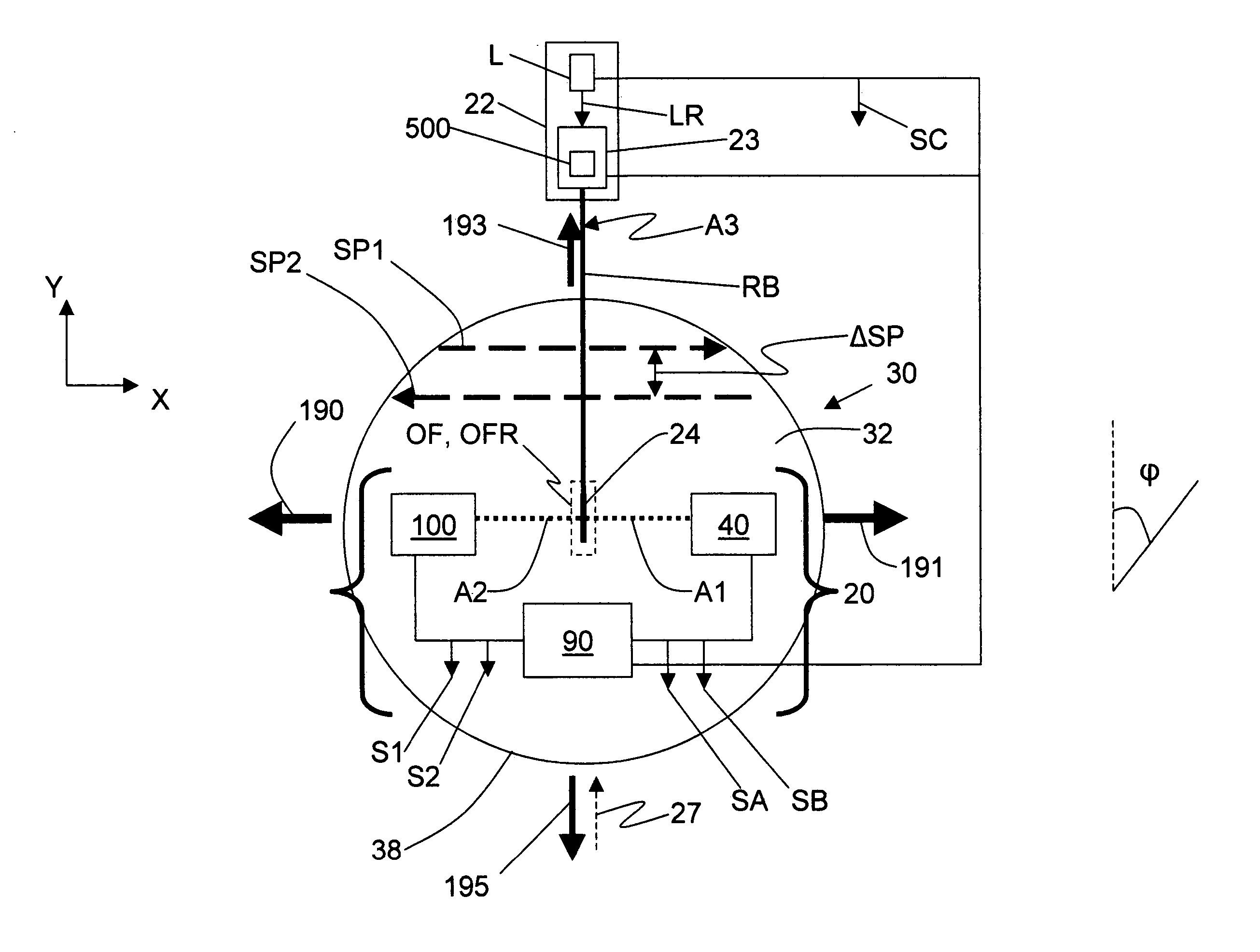
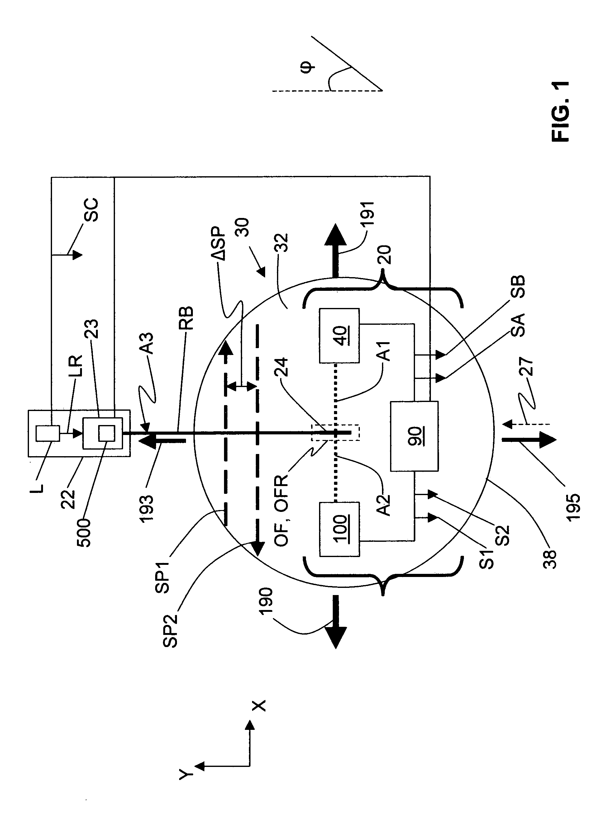
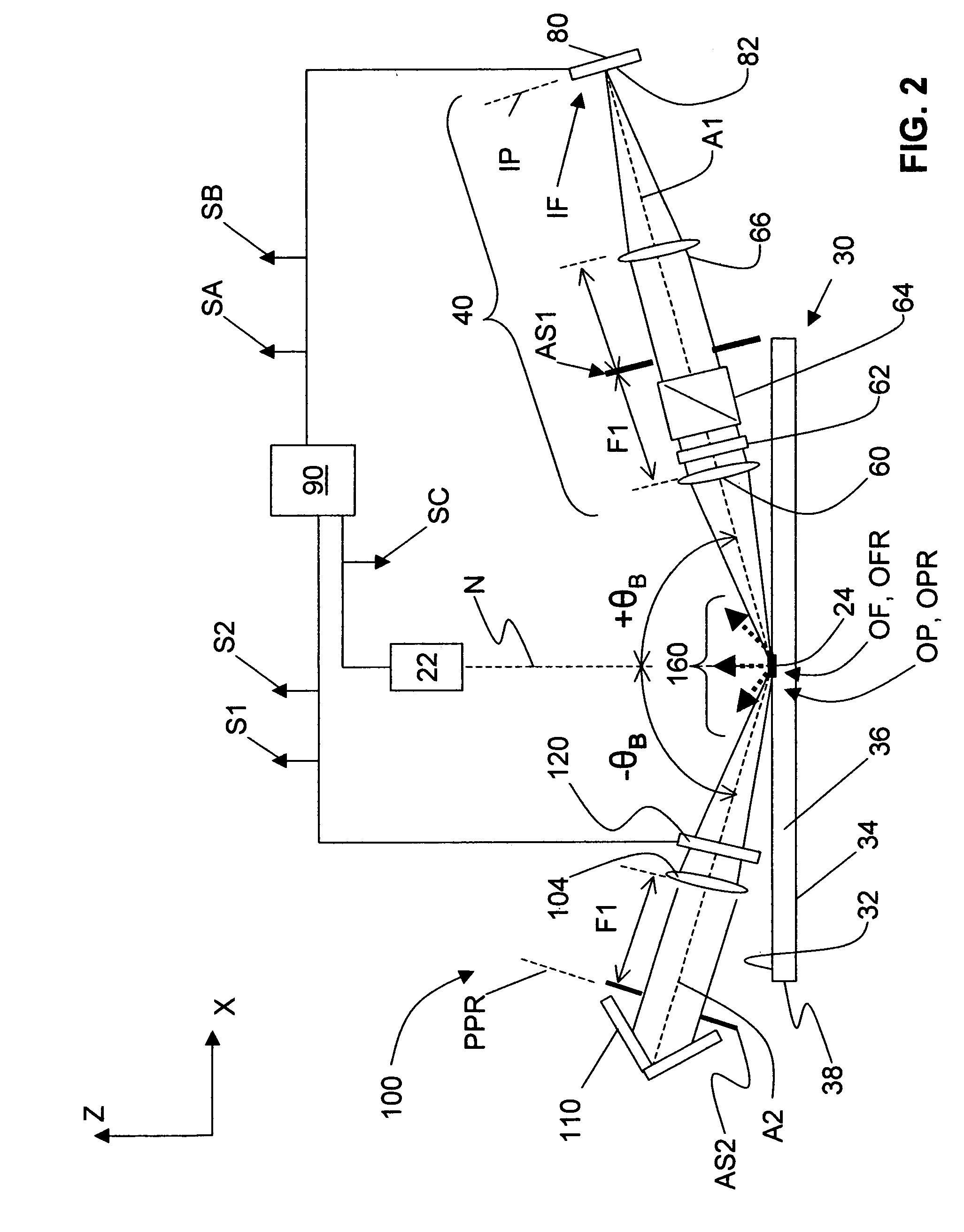
[0033] The present invention relates to apparatus for and methods of remotely measuring the temperature of a specular surface and has particularly utility in the field of laser thermal processing (LTP). Here, a “specular surface” means a surface that is either entirely or substantially flat and reflecting, as opposed to one that is substantially rough and scattering. These criteria depend on the wavelengths and angles used to measure the properties of the surface.

[0034] A preferred embodiment of the invention utilizes relatively high angles of incidence and wavelengths that are long compared to the surface undulations on the substrate. This choice of variables renders the surface more specular-like and less diffuse-like or scattering-like than it would be at shorter wavelengths and smaller (e.g., normal or near-normal) incident angles. In the example embodiments discussed below, the substrate is a silicon wafer undergoing LTP. However, the present invention is not limited to a subs...


PUM

PropertyMeasurementUnit
temperatureaaaaaaaaaa
surface temperaturesaaaaaaaaaa
temperatureaaaaaaaaaa

Abstract

Methods and apparatus for remotely measuring the temperature of a specular surface are disclosed. The method includes taking two different measurements of P-polarized radiation emitted from the surface at or near the Brewster angle associated with the surface. The first measurement (SA) collects and detects a first amount of radiation emitted directly from a surface portion using a collection optical system. The second measurement (SB) includes the first amount of radiation and adds a quantity of radiation collected at or near the Brewster angle and reflected from the surface. This is accomplished with a retro optical system with a round-trip transmission t2 that retro-reflects a quantity of radiation received from the surface portion back to the same surface portion where it is reflected and combined with the first amount of radiation collected by the collection optical system. Measurements SA and SB and the transmission, t2, are used to determine the surface emissivity (ξ). A calibration curve is then used that relates the ratio of the first measurement SA to the surface emissivity ξ, (SA / ξ), to surface temperature. The calibration curve is then used to determine the surface temperature from the SA / ξ value.

Description

CROSS-REFERENCE TO RELATED APPLICATIONS [0001] The present invention is related to the following patents and patent applications: U.S. Pat. No. 6,747,245 (the '245 patent), entitled “Laser Scanning Apparatus and Method for Thermal Processing”; U.S. patent application Ser. No. 10 / 787,664, entitled “Laser Scanning Apparatus and Methods for Thermal Processing”, filed on Feb. 26, 2004; U.S. patent application Ser. No. 10 / 806,014, entitled “Laser Scanning Apparatus and Methods for Thermal Processing”, filed on Mar. 22, 2004, and published as U.S. Patent Application Serial No. 2004 / 0173585 on Sep. 9, 2004; U.S. patent application Ser. No. 10 / 674,106, entitled “Method of Annealing Undoped Silicon Substrates”, filed on Sep. 29, 2003; and U.S. patent application Ser. No. 10 / 762,861, entitled “Laser Thermal Annealing of Lightly Doped Silicon Substrates,” filed on Jan. 22, 2004, all of which are assigned to the common Assignee Ultratech, Inc. of San Jose, Calif., and all of which are incorpora...

Claims


Application Information

Patent Timeline
Patent Type & Authority Applications(United States)
IPC IPC(8): B23K26/04
CPCG01J5/0003G01K11/125G01J2005/0077G01J5/58
Inventor MARKLE, DAVID A.
Owner ULTRATECH INT INC
Learn More