System and method for dealing with ground fault conditions that can arise in an electrical propulsion system

a technology of electrical propulsion system and ground fault, which is applied in the direction of braking system, testing circuit, instruments, etc., can solve problems such as excessive leakage current, component failure, and electrical insulation degradation

Active Publication Date: 2006-11-16
GENERAL ELECTRIC CO
View PDF21 Cites 47 Cited by
  • Summary
  • Abstract
  • Description
  • Claims
  • Application Information

AI Technical Summary

Problems solved by technology

These components may fail over time due to various reasons, one of them being electrical grounds that may be caused by insulation degradation.
For example, locomotives may operate in environments subject to varying conditions, such as those causative of freezing and thawing, which can degrade an electrical insulation exposed to such varying conditions by causing cracks.
The propulsion system of a locomotive has many insulated windings, and excessive leakage current could develop over time due to various factors, such as aging, moisture, abrasions, dirt build-up and the like.
This is especially true for the traction motors since moisture often gets into these components because of their location and exposure to relatively harsh environmental conditions.
Failures due to excessive electrical leakage currents in an electrical system of locomotives are a leading cause of system shutdowns and locomotive mission failures.
Within the propulsion drive system, ground faults can occur in one or several components, which include generator,

Method used


Image

  • System and method for dealing with ground fault conditions that can arise in an electrical propulsion system
  • System and method for dealing with ground fault conditions that can arise in an electrical propulsion system
  • System and method for dealing with ground fault conditions that can arise in an electrical propulsion system

Examples


Embodiment Construction

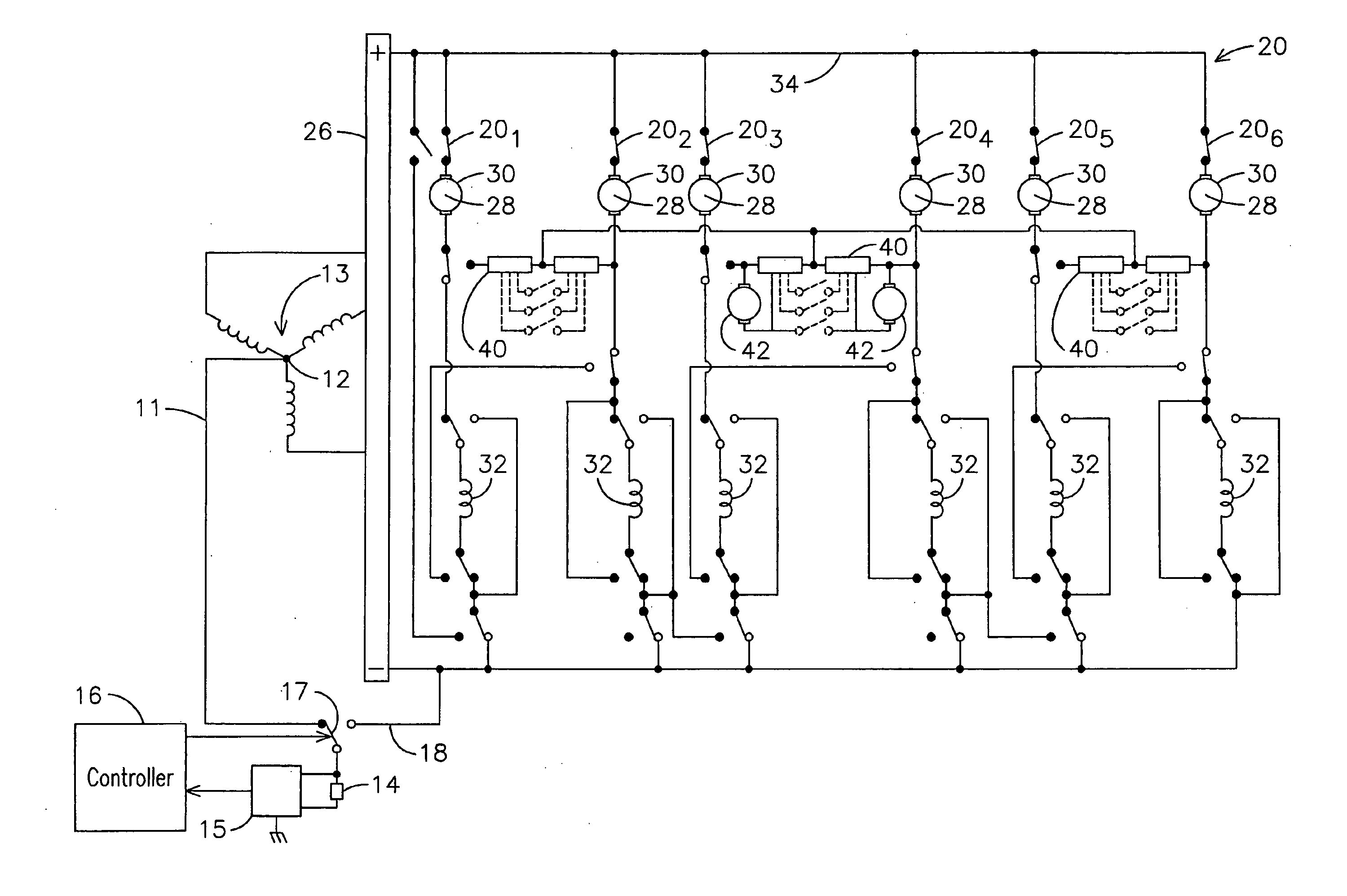
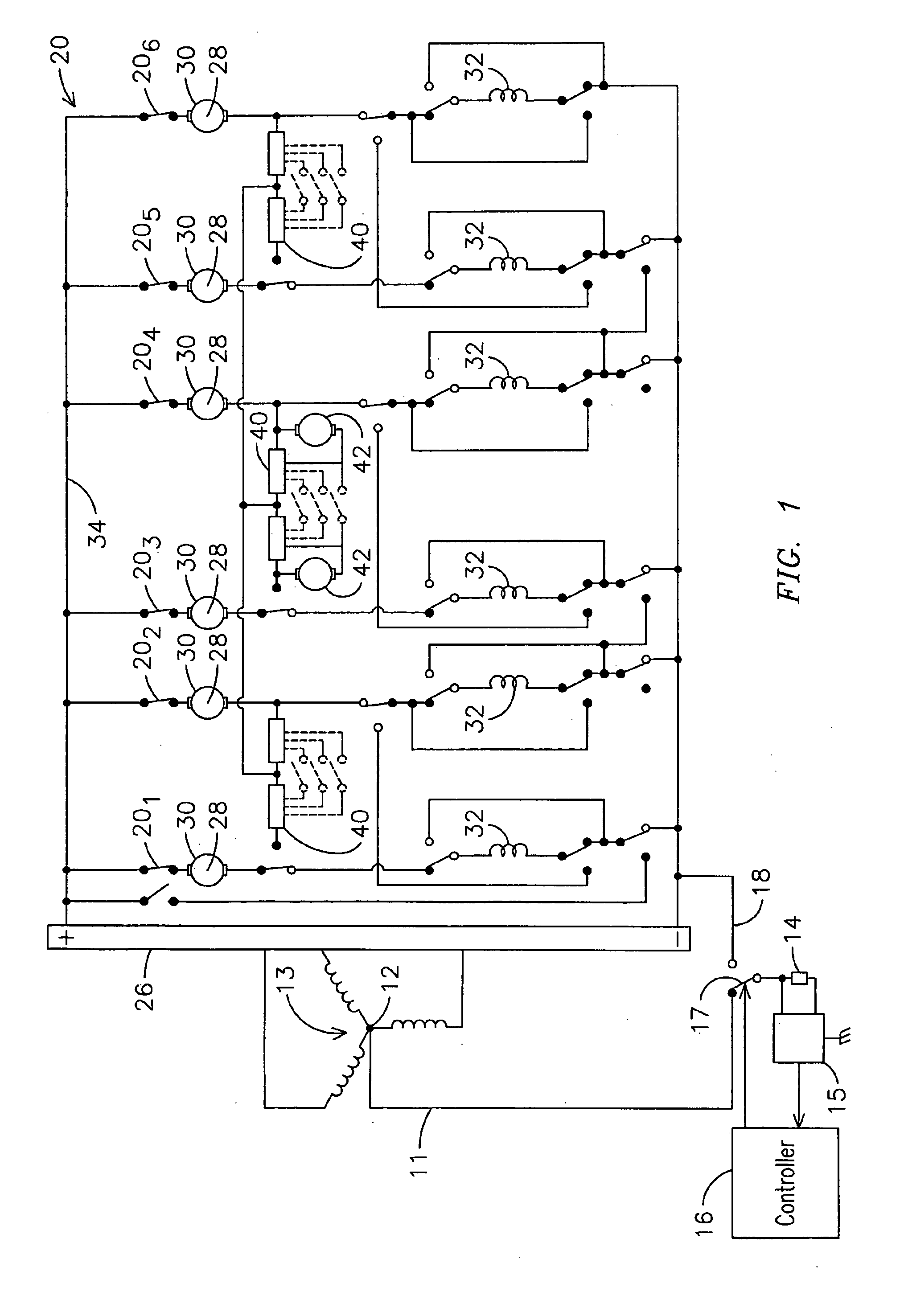
[0011]FIG. 1 is a schematic circuit diagram of a locomotive electrical system that, for purposes of example, comprises a propulsion system 20, such as may be configured for a typical DC (direct current) drive locomotive. Propulsion system 20 comprises a three-phase electromotive machine 13 (which may comprise a motor or generator, for example, and in the embodiment of FIG. 1 comprises a wye-connected generator 13 driven by a prime mover, such as a diesel engine (not shown). Tractive effort may be controlled by varying the excitation current, hence the output voltage, of machine 13. The AC (alternating current) voltage from generator 13 is then rectified by a rectifier 26 to produce DC voltage. Traction motors 28 are usually series field DC traction motors each with an armature 30 and a field winding 32. There are typically four or six traction motors in a locomotive propulsion drive system 20, depending on the application, connected in parallel to a DC bus 34 across the rectified DC...


PUM


Abstract

A method and system is provided for detecting and performing diagnostics regarding an incipient ground fault that may occur in an electrical propulsion system of a traction vehicle, such as a locomotive, transit vehicle, or off-highway vehicle. The method allows providing a first ground connection for the electrical propulsion system. This first ground connection forms a grounding path generally used by the electrical propulsion system during normal operation. The method further allows providing a second ground connection for the electrical propulsion system. This second ground connection forms a grounding path selectively usable in lieu of the first ground connection. A control strategy is defined for switching between the first ground connection and the second ground connection. A respective leakage current associated with at least one of the first and second ground connections may be monitored. Switching between the first and second ground connections may be controlled based on the monitored leakage current associated with at least one of the first and second ground connections.

Description

FIELD OF THE INVENTION [0001] The present invention is generally related to electrical propulsion systems for traction vehicles, and, more particularly, to a system and method for detecting and dealing with ground fault conditions that can arise in the electrical propulsion system of a traction vehicle. BACKGROUND OF THE INVENTION [0002] Locomotives and transit vehicles, as well as other large traction vehicles used for heavy haul applications (off-highway trucks), commonly use an electrical propulsion system that includes various high power electrical components, such as generators, rectifiers, converters, traction motors, dynamic braking grids, cooling blowers, and the like. These components may fail over time due to various reasons, one of them being electrical grounds that may be caused by insulation degradation. For example, locomotives may operate in environments subject to varying conditions, such as those causative of freezing and thawing, which can degrade an electrical ins...

Claims


Application Information

Patent Timeline
IPC IPC(8): B60T8/34
CPCB60L2200/26B60L9/005
Inventor LINEBACH, MARK ALANKUMAR, AJITH KUTTANNAIRWORDEN, BRET DWAYNEMCGARRY, JEREMY T.ZARELLA, SCOTT JOSEPH
Owner GENERAL ELECTRIC CO
Why Eureka
Try Eureka