Light emitting apparatus and vehicle lamp

a technology of light emitting apparatus and vehicle lamp, which is applied in the direction of discharge tube/lamp details, discharge tube luminescnet screens, electric discharge lamps, etc., can solve the problems that the light produced by the semiconductor light emitting device cannot be applied efficiently outside the light emitting apparatus, and the ultraviolet light intensifies the degradation of the resin. achieves the effect of high luminous efficiency

Inactive Publication Date: 2006-11-16
KOITO MFG CO LTD
View PDF3 Cites 69 Cited by
  • Summary
  • Abstract
  • Description
  • Claims
  • Application Information

AI Technical Summary

Benefits of technology

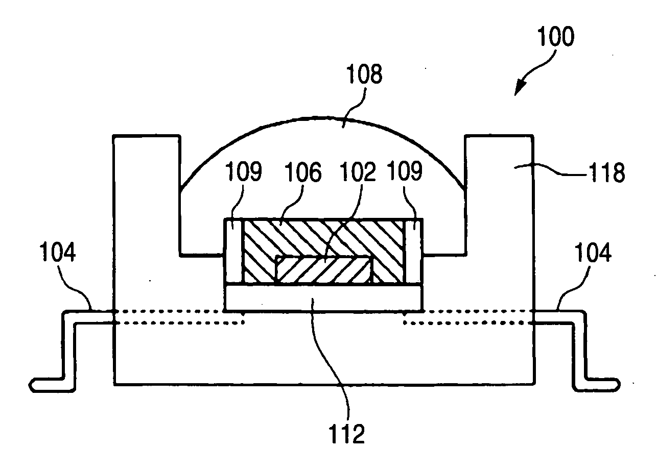
[0010] Therefore, in one or more embodiments of the invention provide a light emitting apparatus configured such that the light deterioration of the device protective layer has been suppressed and the refractive index of the device protective layer has been raised, and thereby the light produced by the light emitting device is extracted efficiently, and a vehicle lamp high in luminous efficiency using the same.
[0021] A light emitting apparatus in accordance with one or more embodiments of the present invention is configured such that the light degradation of the device protective layer has been suppressed, and the refractive index of the device protective layer has been raised, and thereby the light produced by the light emitting device can be extracted efficiently. By using the light emitting apparatus, it is possible to provide a vehicle lamp with a high luminous efficiency.

Problems solved by technology

In such a light emitting apparatus as described above, the following problem has become noticeable: ultraviolet light intensifies the light degradation of the resin for use in the transparent binder as compared with visible light.
As a result, there are some cases where a part of the light produced by the semiconductor light emitting device is not applied to the phosphor in the device protective layer.
For this reason, there are some cases where the light produced by the semiconductor light emitting device cannot be applied efficiently outside the light emitting apparatus.

Method used


Image

  • Light emitting apparatus and vehicle lamp
  • Light emitting apparatus and vehicle lamp
  • Light emitting apparatus and vehicle lamp

Examples


example 1

[0094] To a mixed solution of 1.0 g of tetraethoxysilane, 7.0 g of isopropyl alcohol, and 0.25 g of alumina particles with a primary particle diameter of 50 nm, 0.18 g of 0.1N-HCl was added and stirred. The stirred mixed dispersion solution was formed in a film on a quartz substrate. The film-formed substrate was cured and sintered in a 150° C. oven, to manufacture a sample for evaluation. The evaluation results are shown in Table 1.

example 2

[0095] To 1.0 g of perhydropolysilazane, 0.25 g of alumina particles with a primary particle diameter of 50 nm were added, mixed and dispersed, and the mixture was formed in a film on a quartz substrate. The film-formed substrate was cured and sintered in a 150° C. oven, and then, subjected to a 90° C. 80% RH 3-hour treatment to manufacture a sample for evaluation. The evaluation results are shown in Table 1.

example 3

[0096] To perhydropolysilazane, a dibutyl ether solution containing alumina particles with a primary particle diameter of 50 nm dispersed therein was added. The mixture was adjusted so that the ratio of alumina in the solid content was 80% by weight, and formed in a film on a quartz substrate. The heat treatment conditions for the film were set to be the same as those in Example 2. The evaluation results are shown in Table 1.


PUM

PropertyMeasurementUnit
refractive indexaaaaaaaaaa
particle diameteraaaaaaaaaa
wavelengthaaaaaaaaaa

Abstract

A light emitting apparatus includes a device protective layer including a transparent binder (A) and particles (B), and a light emitting device coated with the device protective layer, characterized in that the transparent binder (A) contains one or more ceramics, and the particles (B) have a smaller particle diameter than the wavelength of the light produced by the light emitting device, and characterized in that the refractive index of the device protective layer is preferably 1.4 or more, the particle diameter of the particles (B) is 100 nm or less, and the device protective layer contains a phosphor therein. The light emitting apparatus can form a vehicle lamp high in luminous efficiency.

Description

[0001] This application claims foreign priority based on Japanese Patent application No. 2005-142398, filed May 16, 2005, the contents of which is incorporated herein by reference in its entirety. BACKGROUND OF THE INVENTION [0002] 1. Field of the Invention [0003] The present invention relates to a light emitting apparatus and a vehicle lamp. [0004] 2. Description of the Related Art [0005] In recent years, from the viewpoints of energy conservation of a light emitting apparatus, and the reduction of environmental load (mercury-free), light emitting apparatuses producing white light using a semiconductor light emitting device and a phosphor have received attention such as disclosed in JP-A-2002-134795 or JP-A-2002-185048. [0006] Such a light emitting device has been improved in luminous efficiency and has become brighter. Therefore, when the transparent binder of the device protective layer is an organic substance such as a resin, light degradation occurs. The following case may occu...

Claims


Application Information

Patent Timeline
Patent Type & Authority Applications(United States)
IPC IPC(8): H01J1/62H01J63/04H01L33/44H01L33/50H01L33/62
CPCB82Y30/00C04B35/6269C04B2235/3217C04B2235/3418H01L33/58C04B2235/5454C04B2235/549H01L33/501H01L33/56C04B2235/483
Inventor TSUTSUMI, YASUAKIDAICHO, HISAYOSHI
Owner KOITO MFG CO LTD
Why Eureka
Try Eureka