Automatic skew correction for differential signals

a technology of differential signals and skew correction, applied in the field of automatic skew correction of differential signals, can solve problems such as skew in signals, and achieve the effect of reducing skew and reducing skew

Inactive Publication Date: 2006-11-16
WARPSPEED CHIPS
View PDF6 Cites 55 Cited by
  • Summary
  • Abstract
  • Description
  • Claims
  • Application Information

AI Technical Summary

Benefits of technology

[0013] The invention relates to a method or apparatus for reducing skew in the receiving end of a differential lane. In accordance with the invention, a skew correction system is incorporated into a transmitter supplying a differential signal as input to a differential lane. With a differential termination at the receiving end of the differential lane, the skew corre

Problems solved by technology

However, when a pair of lines have dissimilar path delays, the differential signal will be skewed at the r

Method used


Image

  • Automatic skew correction for differential signals
  • Automatic skew correction for differential signals
  • Automatic skew correction for differential signals

Examples


Embodiment Construction

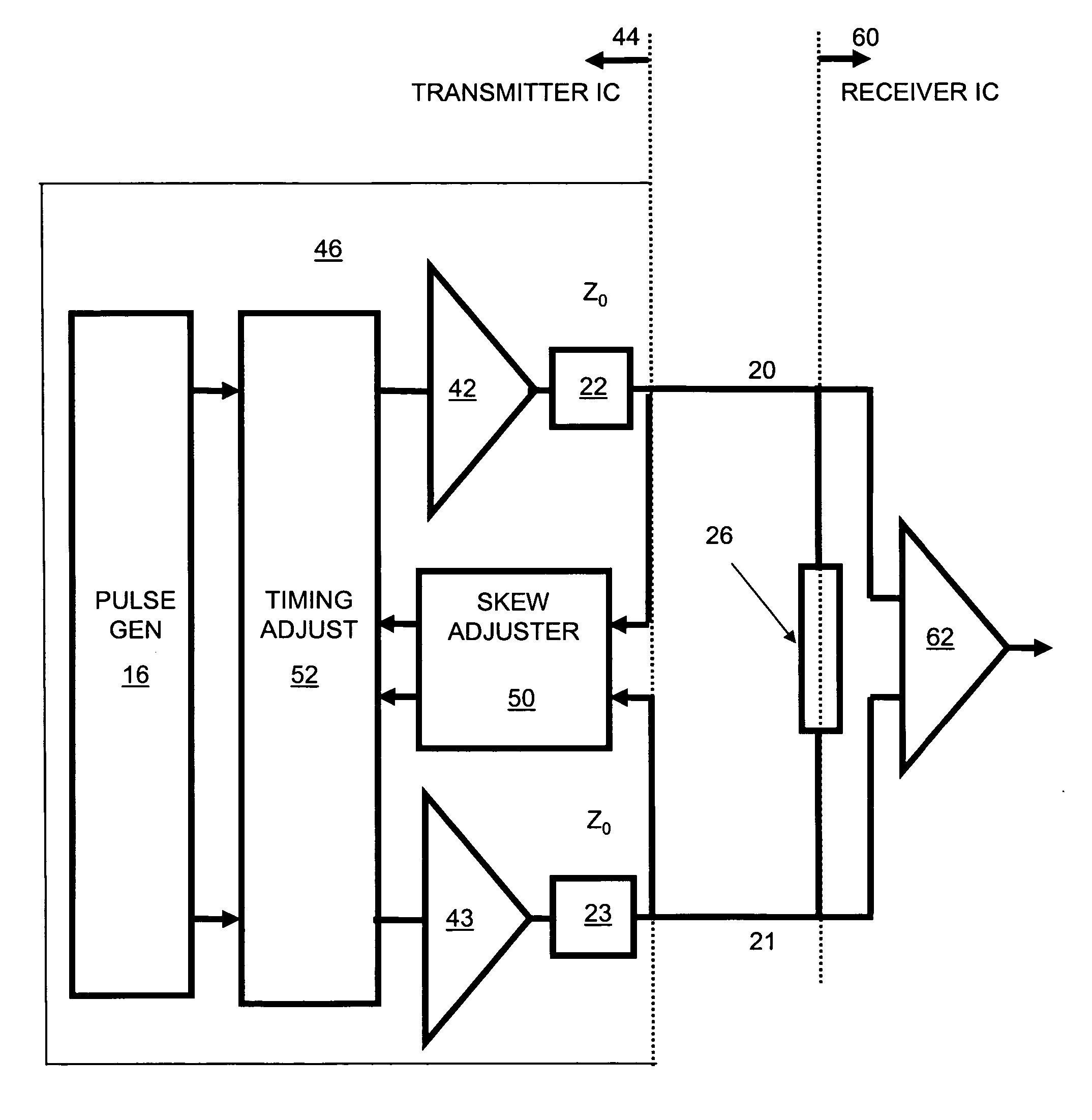
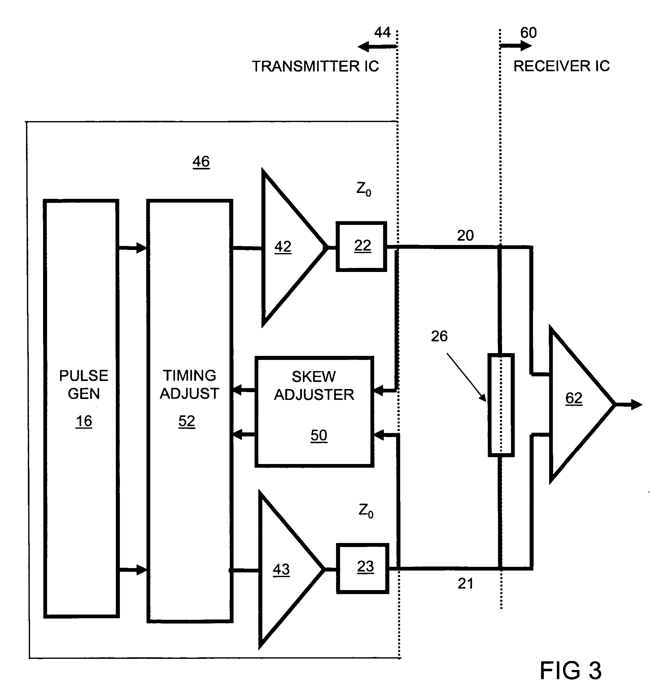
[0035]FIG. 3 depicts a transmitter IC 44 for transmitting a differential signal to a receiver IC 60 via a differential lane formed by a pair of lines 20 and 21. The receiver ends of the lines 20 and 21 are connected to a termination 26, and a differential input circuit 62 of receiver IC 60. Complementary edges of the differential signal on lines 20 and 21 ideally should arrive concurrently at receiver 60, but due to differences in lines 20 or 21, the complimentary edges can arrive at different times. When the timing of the differential signal arriving at receiver 60 exhibits such skew, termination 26 reflects the signal edges back toward transmitter 44.

[0036] Transmitter IC 44 includes a skew correction system 46 in accordance with the invention that monitors the signal reflections returning to transmitter 44 to detect any skew in the differential signal input to receiver IC 60 and adjusts the relative timing of the complementary signal edges as they depart transmitter IC 44 to eli...


PUM


Abstract

A skew correction system incorporated into a transmitter forwarding a differential signal on a differential lane monitors returning signal reflections when the receiving end of the differential lane is appropriately terminated. Based on an analysis of the reflections, the skew correction system adjusts the relative timing of complementary edges of the differential signal departing the transmitter so as to substantially eliminate skew at the receiving end of the differential lane.

Description

CROSS-REFERENCE TO RELATED APPLICATION [0001] This application claims benefit of U.S. Provisional Application No. 60 / 680,877 filed May 13, 2005, the entire disclosure of which is hereby incorporated by reference herein for all purposes.BACKGROUND OF THE INVENTION [0002] 1. Field of the Invention [0003] The invention relates in general to methods and circuits for sensing and correcting skew between the two signals in a differential lane. [0004] 2. Description of Related Art [0005] In high-speed digital applications it is common to use differential inputs and outputs to interconnect integrated circuits at the next higher level of integration (e.g. circuit board or multi-chip module). The reason for this is that differential signaling offers relative immunity to noise and drift that would otherwise have negative impact on the signal integrity of the lane carrying the high-speed information. [0006] It is, however, known that this relative immunity to noise and drift can be compromised b...

Claims


Application Information

Patent Timeline
IPC IPC(8): H04B3/00
CPCG01R31/31706G01R31/31725H03K5/151H04L25/085H04L25/0272H04L25/0292H03K5/156
Inventor FRISCH, ARNOLD M.
Owner WARPSPEED CHIPS
Why Eureka
Try Eureka