
Apparatus and method for dynamic diversity based upon receiver-side assessment of link quality

Inactive Publication Date: 2006-11-16
DSP GROUP
View PDF10 Cites 27 Cited by
  • Summary
  • Abstract
  • Description
  • Claims
  • Application Information

AI Technical Summary

Benefits of technology

[0012] There are a number of advantages associated with the technique of the invention. First, since the technique of the invention is implemented at the receiver, it does not interfere with traditional transmitter-side link-enhancing techniques, such as transmitter power control and packet retransmission. Second, the dynamic diversity technique of the invention allows the communication system to significantly enhance its ability to maintain a reliable link in adverse channel conditions without sacrificing the data transfer rate. The technique also allows a receiver to operate at an improved data rate under a given channel condition, compared to the conventional switched diversity, selection diversity or non-diversity configurations. The technique of the invention facilitates the consumption of considerably less power than a full diversity implementation without a significant sacrifice in throughput. Advantageously, the dynamic mode selection technique of the invention can utilize various physical (PHY) layer as well as medium access control (MAC) layer parameters to identify a change in the quality of the communication link.

Problems solved by technology

A no diversity configuration allows for the simplest implementation and results in the lowest power consumption.
On the other hand, in the absence of a diversity configuration, the received signal is vulnerable to fading.
These advantages and disadvantages relate to tradeoffs between the quality of the signal reception and the amount of power consumed.
For mobile wireless communication devices there are continuing pressures to reduce power consumption.

Method used


Image

  • Apparatus and method for dynamic diversity based upon receiver-side assessment of link quality
  • Apparatus and method for dynamic diversity based upon receiver-side assessment of link quality
  • Apparatus and method for dynamic diversity based upon receiver-side assessment of link quality

Examples


Embodiment Construction

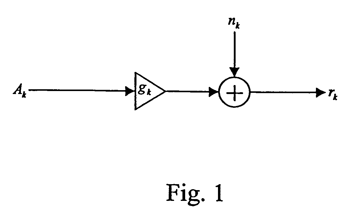
[0022] Consider the representative quadrature amplitude modulation (QAM) system depicted in FIG. 1. The received sample rk is given by

rk=gkAk+nk   (1)

where gk represents the fading in the wireless medium, Ak is the QAM symbol and nk is the additive noise. All variables are complex-valued in general. This is a general description of QAM symbols being transmitted over a fading channel corrupted by additive noise. As such, equation (1) can be either a time-domain or a frequency-domain model. In a practical wireless system that utilizes a finite number, say N, fixed frequency bins, the model of equation (1) is applied with an underlying assumption that the k-th symbol transmission occupies the (k modulo N)-th frequency bin. Bins are used in a successive manner from the first bin to the last one, and then back to the first one and so on. Among specific examples of the latter system are frequency division multiplexing (FDM) and orthogonal frequency division multiplexing (OFDM) systems....


PUM


Abstract

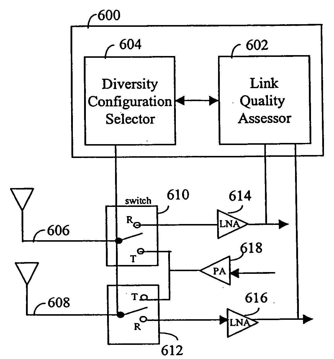
An apparatus for dynamic diversity signal reception based upon receiver-side link quality assessments includes two or more antennae. At least one switch is connected to the two or more antennae. A dynamic diversity controller is connected to the at least one switch. The dynamic diversity controller includes a link quality assessor to assess link quality and generate a link characterization value. A diversity configuration selector, responsive to the link characterization value, selectively activates the at least one switch to implement a dynamic diversity configuration. The link quality assessor includes a signal strength analyzer, a modem detector, and / or a MAC layer analyzer to assess the received signal and generate the link characterization value.

Description

[0001] This application claims priority to U.S. provisional patent application Ser. No. 60 / 355,266, filed Feb. 9, 2002, the entire content of which is incorporated herein by reference.BRIEF DESCRIPTION OF THE INVENTION [0002] This invention relates generally to wireless signal processing. More particularly, this invention relates to dynamic diversity selection based upon receiver-side link quality assessments. BACKGROUND OF THE INVENTION [0003] Diversity is a form of signal reception in which the output signals from two or more independent antennae are combined to provide a signal that is less likely to fade. Various diversity schemes are known in the art. By way of example, various diversity schemes will be discussed in connection with two receive antennae. Each of these diversity schemes is equally applicable to multiple receive antennae. [0004] When there is only one antenna there is no diversity. A no diversity configuration allows for the simplest implementation and results in ...

Claims


Application Information

Patent Timeline
IPC IPC(8): H04B1/02H04B7/08H04L1/00H04L1/20
CPCH04B7/0811H04B7/0814H04L1/206H04L1/0015H04L1/0001
Inventor MOON, JAEKYUNKIM, YOUNGGYUNBRICKNER, BARRETT J.EDWARDS, PAUL C.BUTENHOFF, MICHAEL E.
Owner DSP GROUP
Learn More