Devices and methods for conditioning or vaporizing liquid fuel in an intermittent combustion engine

a technology of liquid fuel and intermittent combustion engine, which is applied in the direction of machines/engines, combustion-air/fuel-air treatment, electric control, etc., can solve the problems of diesel fuel, prone to combustion, and the design of most engine designs consume fuel less efficiently than diesel fuel, so as to increase fuel efficiency and emission quality

Inactive Publication Date: 2006-11-23
YOSHIMOTO HITOSHI
View PDF19 Cites 20 Cited by
  • Summary
  • Abstract
  • Description
  • Claims
  • Application Information

AI Technical Summary

Benefits of technology

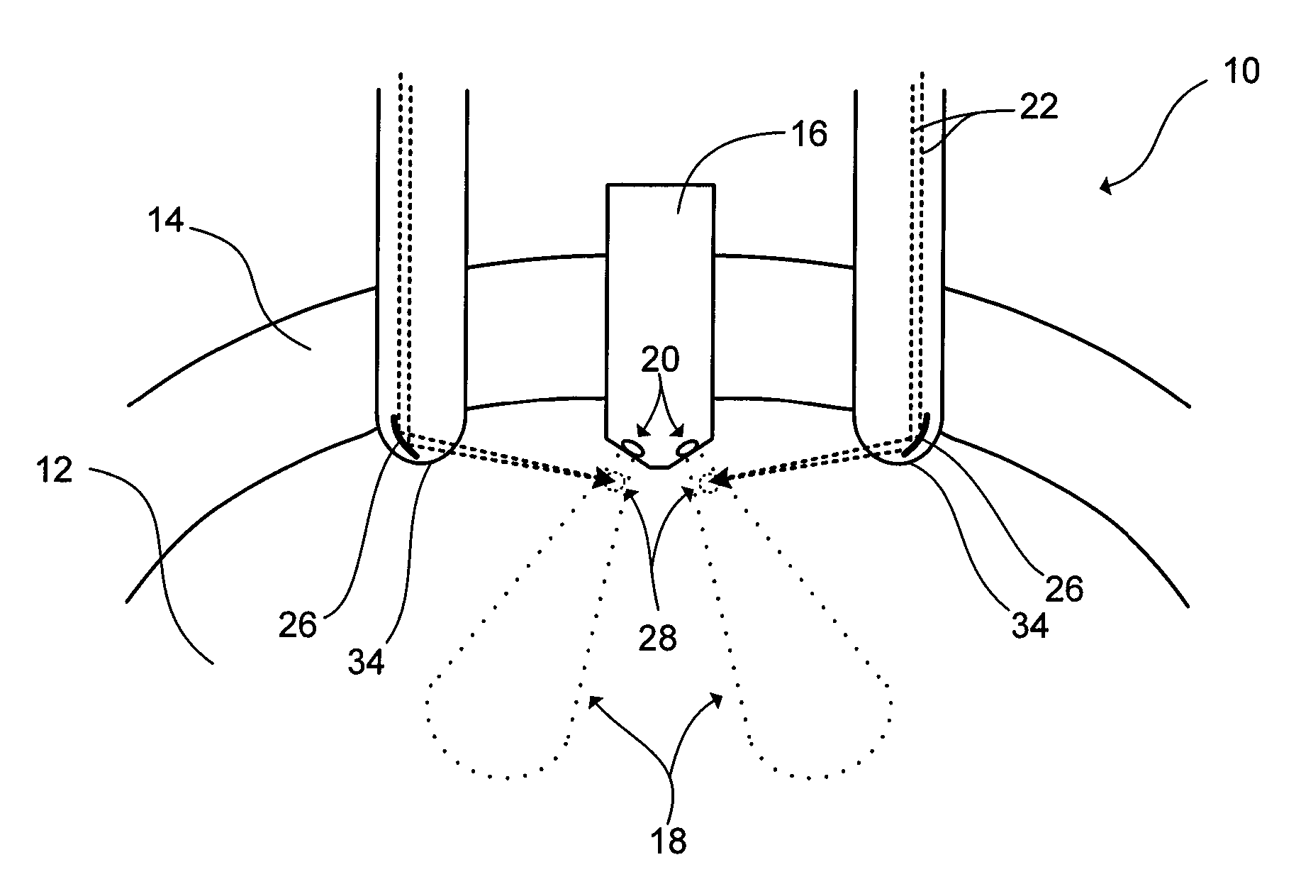
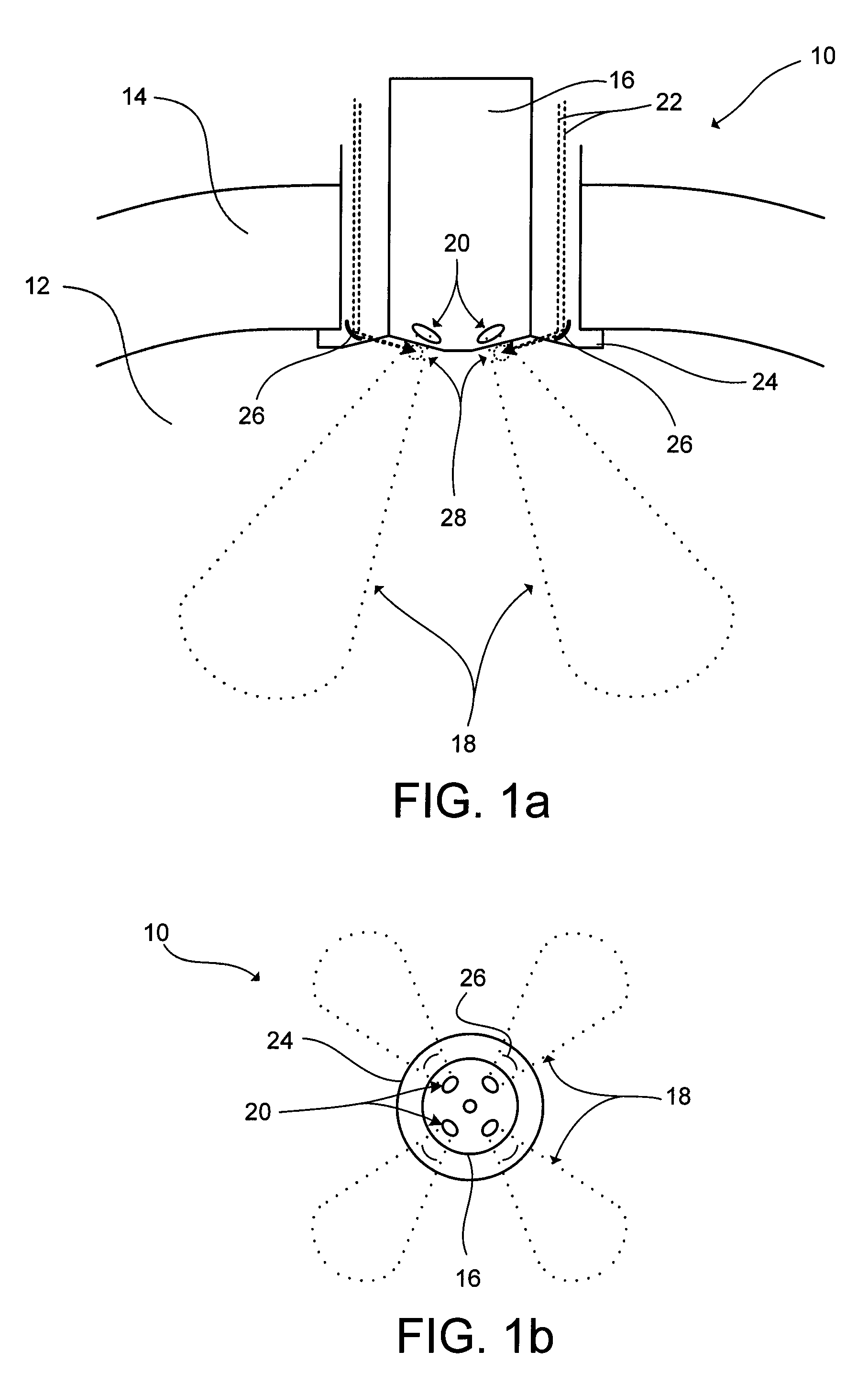
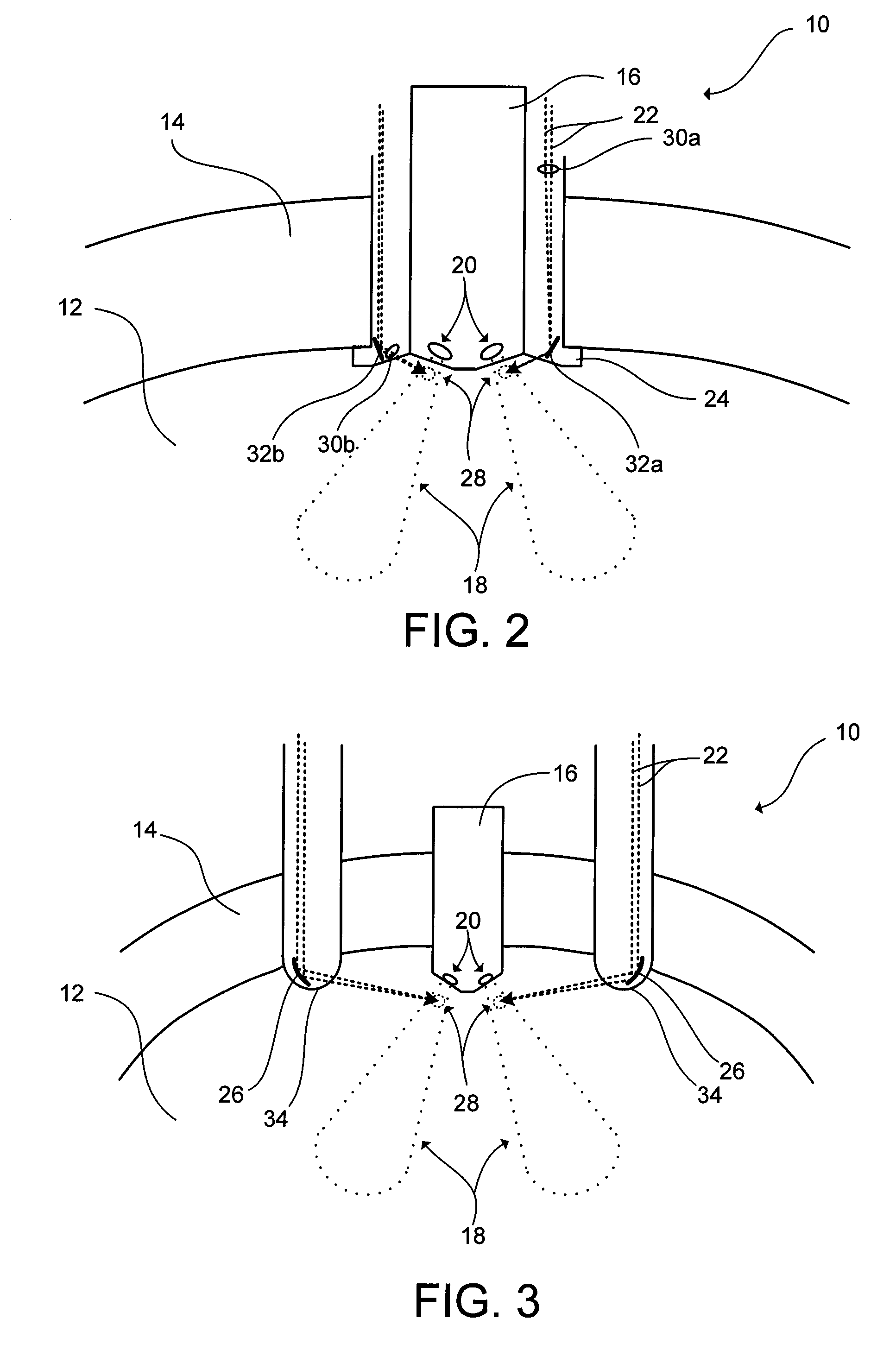
[0007] It has been recognized that it would be advantageous to develop a fuel conditioning device for more completely vaporizing fuel prior to ignition to thereby increase the fuel efficiency and emission quality of intermittent combustion engines.

Problems solved by technology

However, to date, most engine designs consume fuel less efficiently than is theoretically possible.
Diesel fuels, on the other hand, tend to combust when subjected to heat and pressure from a combustion chamber, where the temperature increases due to compression, which allows the fuel to be converted from a liquid phase to a vapor phase.
This is particularly a problem with the diesel engine, as the fuel is injected into the combustion chamber in liquid spray form, is vaporized, and becomes self-ignited within the same combustion cycle.
Even under normal operating conditions, diesel fuel tends to self-ignite before vaporization is complete.
Further, when cold starting a diesel engine, the vaporization is even less complete, exacerbating problems associated with poor emissions.
For example, soot can build up due to incomplete combustion of the fuel.
Additionally, an increase in other undesirable exhaust emissions can result when the fuel is not completely consumed in the fuel combustion process.
However, these additives can increase the cost of already expensive fuels and may not provide optimal results.

Method used


Image

  • Devices and methods for conditioning or vaporizing liquid fuel in an intermittent combustion engine
  • Devices and methods for conditioning or vaporizing liquid fuel in an intermittent combustion engine
  • Devices and methods for conditioning or vaporizing liquid fuel in an intermittent combustion engine

Examples


Embodiment Construction

)

[0023] Before the present invention is disclosed and described, it is to be understood that this invention is not limited to the particular structures, process steps, and materials disclosed herein as such process steps and materials may vary to some degree. It is also to be understood that the terminology used herein is used for the purpose of describing particular embodiments only and is not intended to be limiting, as the scope of the present invention will be limited only by the appended claims and equivalents thereof.

[0024] It must be noted that, as used in this specification and the appended claims, the singular forms “a,”“an,” and “the” include plural referents unless the content clearly dictates otherwise.

[0025]“Focusing limit” refers to a focal limit of electromagnetic energy. Generally, electromagnetic energy may only be focused to a point as small as half of its wavelength. Thus, electromagnetic energy focused in the present invention can be focused in a pattern that i...


PUM


Abstract

A device and method for conditioning and/or volumetric heating fuel within an intermittent combustion engine in order to enhance fuel combustion and emission performance is provided. Such a device can include a fuel injector configured to eject a fuel spray having a trajectory within a combustion chamber, an energy source capable of emitting electromagnetic energy, and an optical fiber configured to transmit electromagnetic energy emitted from the energy source into the combustion chamber, and is also configured to cause fuel conditioning.

Description

[0001] The present application is a continuation-in-part of U.S. patent application Ser. No. 11 / 133,147, filed May 18, 2005.FIELD OF THE INVENTION [0002] The present invention relates to improving the emission quality of intermittent combustion engines upon fuel consumption by introducing electromagnetic energy, such as laser energy, within a combustion chamber. BACKGROUND OF THE INVENTION [0003] Hydrocarbon fuels, such as diesel fuel, gasoline, or the like, are useful fuels for intermittent combustion engines. However, to date, most engine designs consume fuel less efficiently than is theoretically possible. Therefore, those in the industry have recognized the potential of significantly improving fuel consumption efficiency and are continuing to develop processes that improve emissions. One area where improvements can be made includes the area of liquid fuel vaporization, particularly with respect to the above mentioned fuels. Typically, gasoline and diesel fuels must be forced int...

Claims


Application Information

Patent Timeline
Patent Type & Authority Applications(United States)
IPC IPC(8): F02B19/00F02B3/00F02M27/00
CPCF02B17/005F02B23/0654F02B23/0669F02B2023/103F02B2275/14Y02T10/123F02D41/064F02M27/06F02P23/04F02P23/045Y02T10/125F02D41/047Y02T10/12
Inventor YOSHIMOTO, HITOSHI
Owner YOSHIMOTO HITOSHI
Why Eureka
Try Eureka