System and method for particulate filter regeneration

A soot, destination technology, applied in the field of systems and methods for particulate filter regeneration, capable of solving problems such as injector degradation, temperature rise of urea injectors, impact on emission quality, etc.

Pending Publication Date: 2020-03-03
FORD GLOBAL TECH LLC
View PDF1 Cites 4 Cited by
  • Summary
  • Abstract
  • Description
  • Claims
  • Application Information

AI Technical Summary

Problems solved by technology

If PF regeneration is scheduled to terminate at the end of the current drive cycle, during the immediately subsequent engine start, the amount of ammonia remaining in the SCR catalyst may be low

Method used


Image

  • System and method for particulate filter regeneration
  • System and method for particulate filter regeneration
  • System and method for particulate filter regeneration

Examples


Embodiment Construction

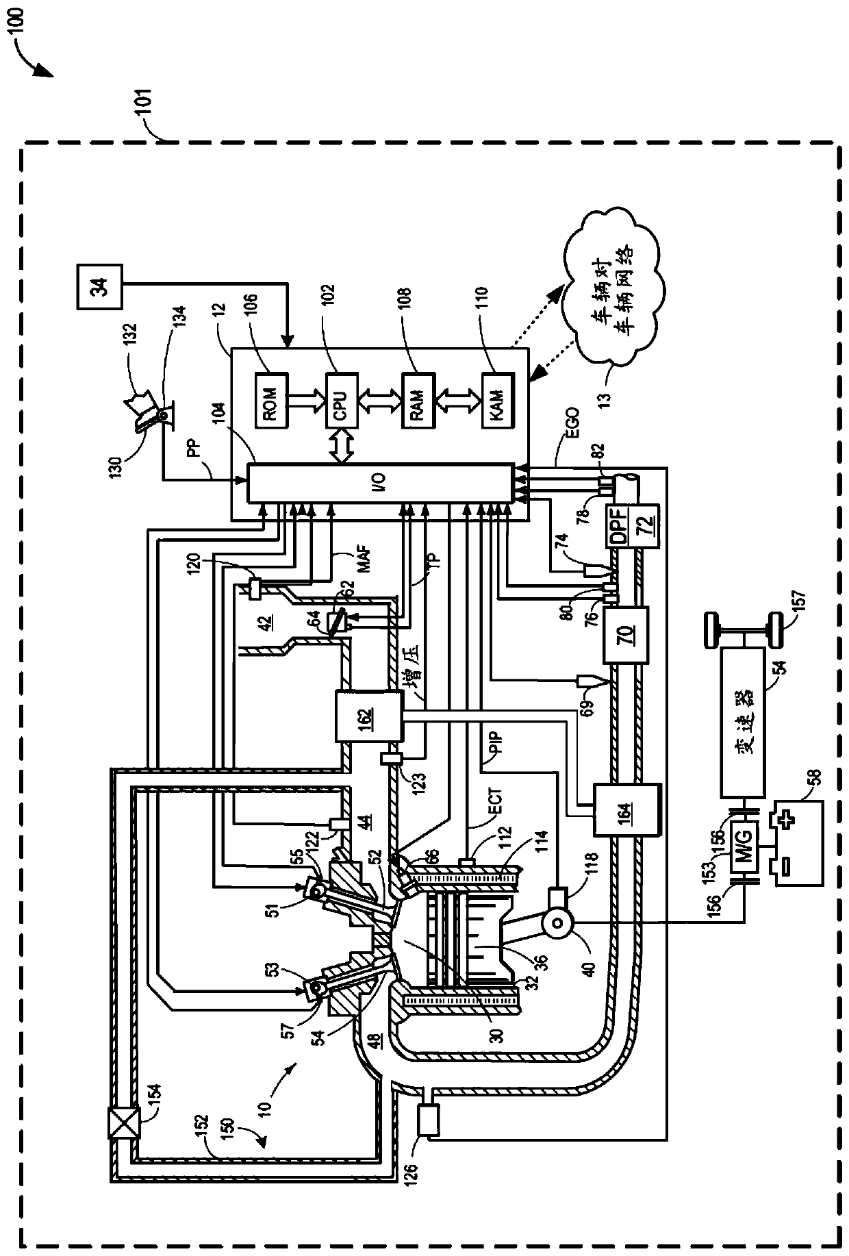
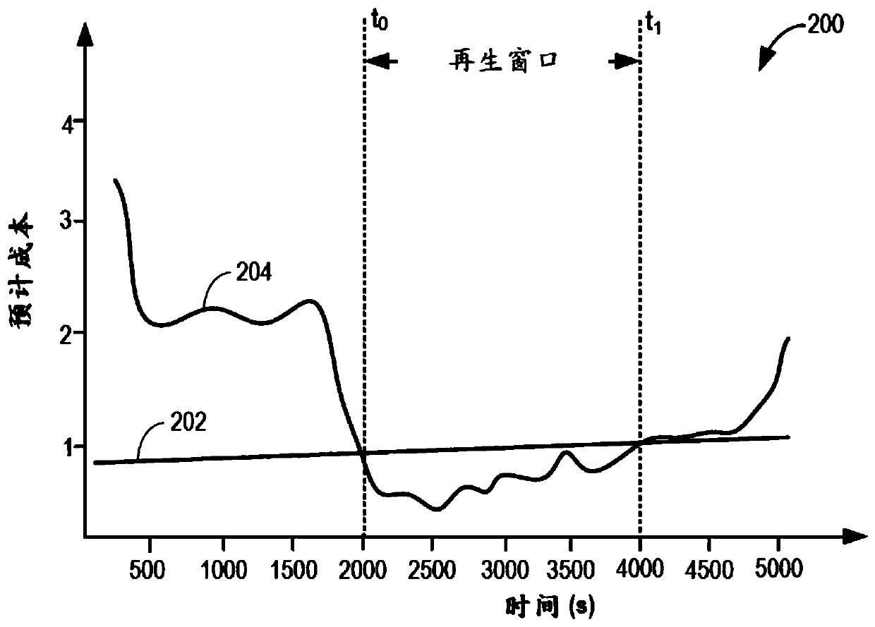
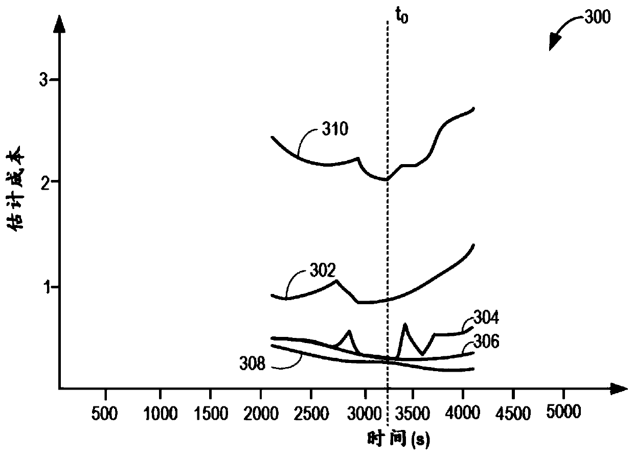
[0015] The following description relates to systems and methods for regenerating a particulate filter (PF) based on predicted vehicle driving conditions and catalyst ammonia storage capacity. PF and Selective Catalytic Reduction (SCR) catalysts can be coupled to figure 1 The exhaust passage of the diesel engine shown. The engine controller can be configured to execute control routines such as figure 2 and image 3 An example routine to opportunistically regenerate the PF and adjust the ammonia storage setpoint and urea injection limit prior to regeneration. figure 2 and image 3 The graph shown in shows the fuel cost associated with performing regeneration and the regeneration variation based on the regeneration start time. Figure 6 An exemplary regeneration of the PF during a drive cycle is shown in .

[0016] now refer to figure 1 , shows a schematic diagram showing one cylinder of a multi-cylinder internal combustion engine 10 that may be included in the propulsion...


PUM


Abstract

The invention provides a system and method for particulate filter regeneration. Methods and systems are provided for regenerating an exhaust particulate filter based on a projected vehicle drive cycleand catalyst ammonia storage level. In one example, a method may include scheduling a PF regeneration during a regeneration window to maintain a threshold ammonia level in an exhaust catalyst, at theend of the drive cycle.

Description

technical field [0001] The present description generally relates to methods and systems for controlling a vehicle engine to perform regeneration of a particulate filter based on predicted vehicle drive cycles and catalyst ammonia storage levels. Background technique [0002] Emission control devices, such as particulate filters (PF) and selective catalytic reduction (SCR) catalysts, can reduce engine soot and NOx emissions by trapping soot particles and reducing NOx to nitrogen and water, respectively. In order to reduce NOx, a reducing agent such as ammonia needs to be present. The particulate filter may be regenerated during engine operation to reduce the amount of trapped particulate matter. Regeneration may be achieved by raising the temperature of the PF to a predetermined level, maintaining the temperature at the predetermined level, and ensuring that the exhaust gas entering the PF has a certain composition to combust or oxidize particulate matter. [0003] Various ...

Claims


Application Information

Patent Timeline
IPC IPC(8): F01N9/00F01N11/00F01N3/023F01N3/20
CPCF01N3/023F01N3/208F01N9/002F01N11/00F01N2250/02F01N2560/021F01N2610/02F01N2610/146F01N2900/12F01N2900/1606F01N3/2066F01N2900/08F01N2900/10F01N2900/102F01N2900/1402F01N2900/1616Y02T10/12Y02T10/40Y02A50/20F01N3/0296F01N2900/1811F01N2900/1814
Inventor 科里·亨德里克森德维什·乌帕德亚迈克尔·布兰登·霍普考
Owner FORD GLOBAL TECH LLC
Why Eureka
Try Eureka