Muffler having fluid swirling vanes

Inactive Publication Date: 2006-11-23
KIM JAY S +1
View PDF29 Cites 11 Cited by
  • Summary
  • Abstract
  • Description
  • Claims
  • Application Information

AI Technical Summary

Benefits of technology

[0020] The vanes are specially curved (at their edges) and shaped for maximal efficiency in producing the swirl effect with minimal fluid flow restriction. The vanes are longitudinally longer at the inner surfaces of the walls of the inlet duct than at the central area of the duct. Thus, the peripheral portions of the vanes are larger and therefore provide more deflection than the smaller, more centrally located portions of the vanes. This is desirable because it more efficiently yields the desired swirl. This is because the swirl produced is essentially exhaust gas rotation about a central axis with the more peripheral gas at peripheral areas of the duct (or chamber) rotating more than the gas at more centrally located areas. Consequently, flow deflection at the peripheral portions of the duct is more effective in producing the desired fluid rotation about the central axis of the duct (and chamber). Similarly, near the central area of the housing the vane portions are smaller producing less deflection and concomitantly less fluid flow restriction at the duct area where swirl can less effectively be produced.
[0021] The lower or trailing edges of the vanes are also curved to streamline the vanes for reduced fluid flow resistance. The curvature is in a direction of from the periphery to the center of the duct (or chamber). Since the peripheral ends of the primary vanes are longer than the central (or inner) ends, the lower or trailing edge is angled in the direction of fluid flow and the curvature thereof is also curved in this direction.
[0022] Additionally, lower end portions and lower medial end portions of the vanes are bent in the direction of the deflection of the fluid flow. The lower end portions and lower medial end portions are thus angled laterally to enhance deflection of the fluid flow. This deflection provided by these lower portions is also very effective in producing swirl because the fluid flow has been previously deflected by upper portions of the primary vanes and has been moving downwardly alongside the vanes until it reaches these lower portions where it is further deflected to add more lateral movement and thereby more rotational movement to the fluid flow.
[0023] Also included are secondary vanes for maximal efficiency in producing the swirl effect with minim

Problems solved by technology

This is in spite of their many disadvantages the more important of which include toxic exhaust emissions and exhaust noise.
Although mufflers can substantially reduce or perhaps even eliminate the exhaust noise, it is commonly believed that they do so at the expense of reduced power output and reduced fuel economy.
However, such systems require retuning of the engine and replacement of major engine system components and are thus impractical for many motor vehicle owners.
Two primary disadvantages of dissipative mufflers are that they lose their effectiveness over time and are expensive to manufacture.
Moreover, dissipative mufflers do not produce good low frequency sound attenuation.
A reactive muffler is inexpensive to manufacture and provides good low frequency sound attenuation but has the disadvantage of producing high backpressure.
Variations on these two basic designs have sought to produce desired sound attenuation without substantially or unacceptably incr

Method used


Image

  • Muffler having fluid swirling vanes
  • Muffler having fluid swirling vanes
  • Muffler having fluid swirling vanes

Examples


Embodiment Construction

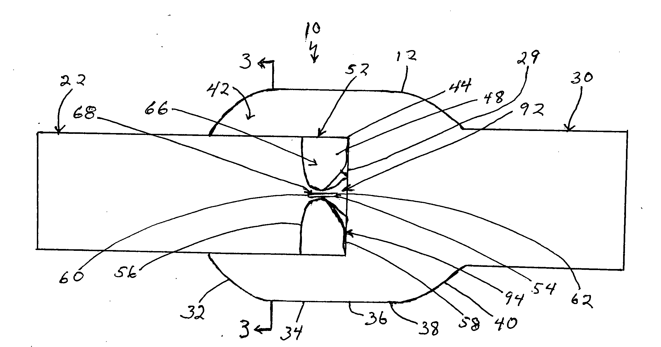
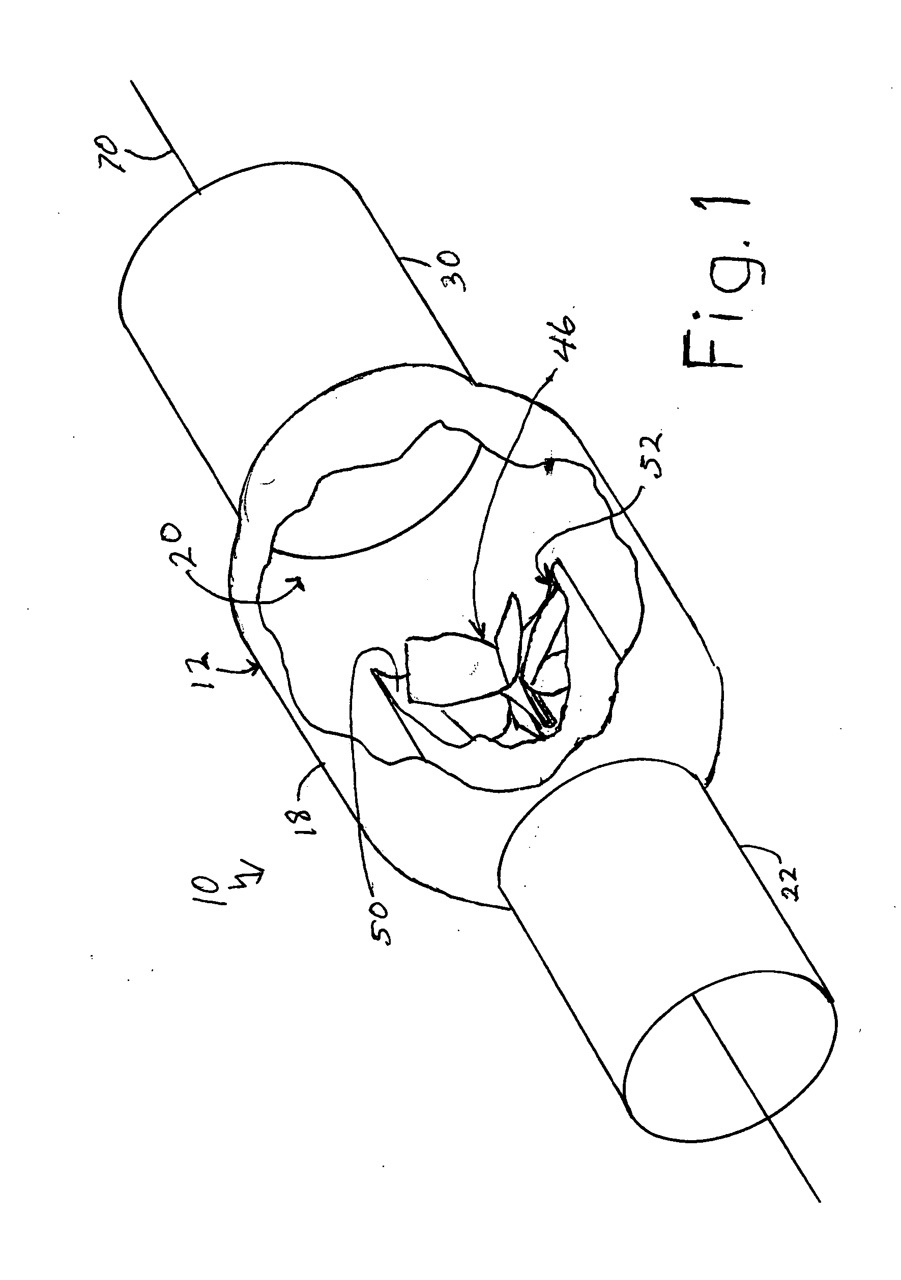
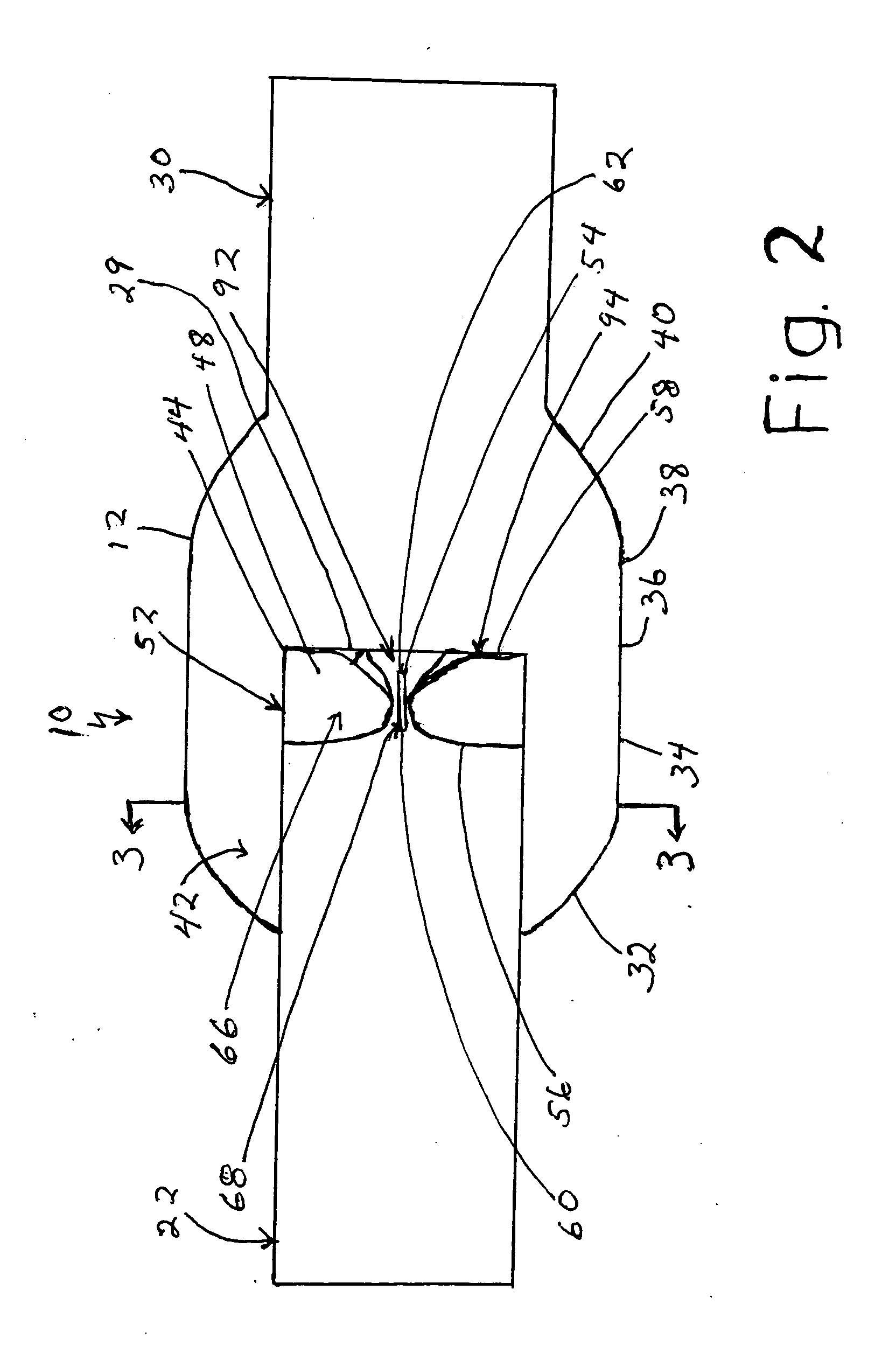
[0036] Referring to the drawings, the muffler of the present invention is generally designated by the numeral 10. The muffler 10 includes a casing 12. The casing 12 is hollow and includes an inlet port 14 and an outlet port 16 at opposite ends thereof. The casing 12 also includes a main body 18 defining an expansion chamber 20 in the casing 12 and located between the inlet port 14 and outlet port 16. An inlet duct 22 is connected to the inlet port 16 and has an inlet end 24 for connection to an exhaust pipe (not shown) to allow exhaust fluid 26 from an internal combustion engine (not shown) to enter the casing 12. The inlet duct 22 extends through the inlet port 14 and has an outlet (or discharge) end 28 for discharge of the exhaust fluid 26 into the expansion chamber 20 which has a larger cross-sectional area than the inlet duct 22 (and inlet port 14), as is typical for conventional mufflers. The casing 12 also includes an outlet duct 30 connected to the outlet port 16 for allowing...


PUM


Abstract

A muffler for an internal combustion engine has a casing forming an expansion chamber therein. An inlet duct is connected to the casing and projects into the expansion chamber and discharges exhaust fluid into the expansion chamber. The casing tapers in an upstream direction to form a pocket for receiving reverse flow of the exhaust gases and to minimize reverse flow from flowing back into the inlet duct in an upstream direction. In the discharge end of the inlet duct are a set of primary vanes and a set of secondary vanes. The vanes are secured to the walls of the duct and extend radially toward the central area of the duct. The vanes are angled in order to deflect the exhaust fluid flow into a swirling movement as it is discharged into the expansion chamber and maintains that swirling movement while passing out of the casing through the outlet duct.

Description

BACKGROUND OF THE INVENTION [0001] The present invention relates generally to mufflers for internal combustion engines of the type commonly used in motor vehicles. More particularly, the present invention relates to such mufflers which provide improved engine combustion efficiency resulting in improved performance and reduced toxic exhaust emissions levels. [0002] Motor vehicles utilizing internal combustion engines continue to be the favored form of transportation to most people in the developed countries of the world. This is in spite of their many disadvantages the more important of which include toxic exhaust emissions and exhaust noise. Although mufflers can substantially reduce or perhaps even eliminate the exhaust noise, it is commonly believed that they do so at the expense of reduced power output and reduced fuel economy. [0003] Designers of exhaust systems have recognized that improving the effectiveness of exhaust gas flow out of the engine can provide improved combustion...

Claims


Application Information

Patent Timeline
IPC IPC(8): F01N1/12
CPCF01N1/12
Inventor KIM, JAY S.HANSON, EDWARD F.
Owner KIM JAY S
Why Eureka
Try Eureka