Method of manufacturing optical fiber

a manufacturing method and technology of optical fiber, applied in the field of manufacturing optical fiber, can solve the problems of difficult mass production efficiency, inability to meet the requirements of hydrogen characteristic, and non-bridging oxygen hole center, etc., and achieve the effect of efficient and reliable production, excellent effect, and insufficient efficiency and accuracy

Inactive Publication Date: 2005-08-30
SUMITOMO ELECTRIC IND LTD
View PDF12 Cites 4 Cited by
  • Summary
  • Abstract
  • Description
  • Claims
  • Application Information

AI Technical Summary

Benefits of technology

[0015]The effect that an optical fiber whose characteristics are fully restrained from deteriorating in a hydrogen atmosphere can be obtained efficiently and reliably, exhibited by the present invention, and the effect will not be obtained unless the glass cooling rate at the time when the optical fiber attains a temperature of 1800° C. is 4000° C./sec or lower. If the glass cooling rate at the time when the optical fiber attains other temperatures (e.g., about 1700° C.) is controlled here, efficiency and accuracy will become insufficient when manufacturing an optical fiber whose characteristics are fully restrained from deteriorating in a hydrogen atmosphere.
[0016]The method of manufacturing an optical fiber in accordance with the

Problems solved by technology

However, when an optical fiber whose core part contains a germanium compound at a high concentration is made by the above-mentioned conventional method, defects such as non-bridging oxygen hole center may occur due to thermal dissociation of Si—O—Ge bonds in the drawing step, whereby the characteristic that the optical fiber does not increase transmission loss for light having a wavelength of 1.38 μm in a hydrogen atmosphere (hereinafter referred to as “hydrogen characteristic”) becomes insufficient.
The occurrence of non-bridging oxygen hole center is remarkably seen when the optical fiber is drawn from larger preform or with a higher line speed, whereby it has been very di

Method used


Image

  • Method of manufacturing optical fiber
  • Method of manufacturing optical fiber
  • Method of manufacturing optical fiber

Examples


example 1

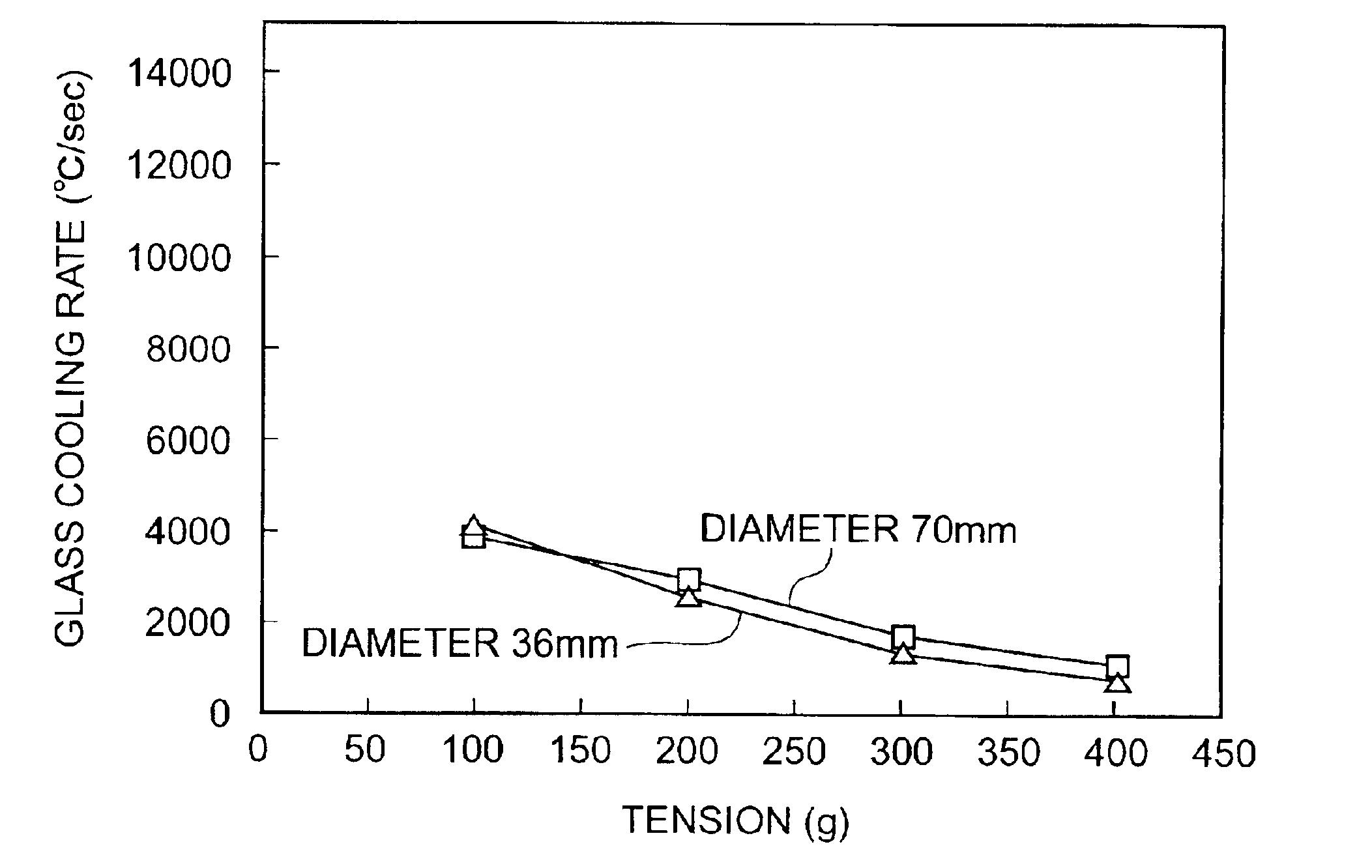
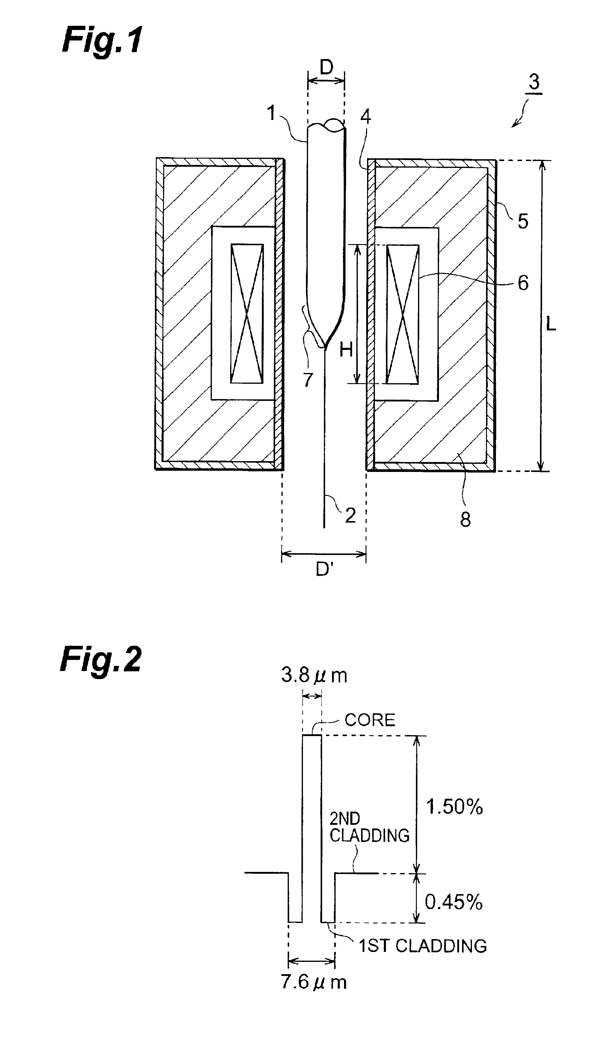
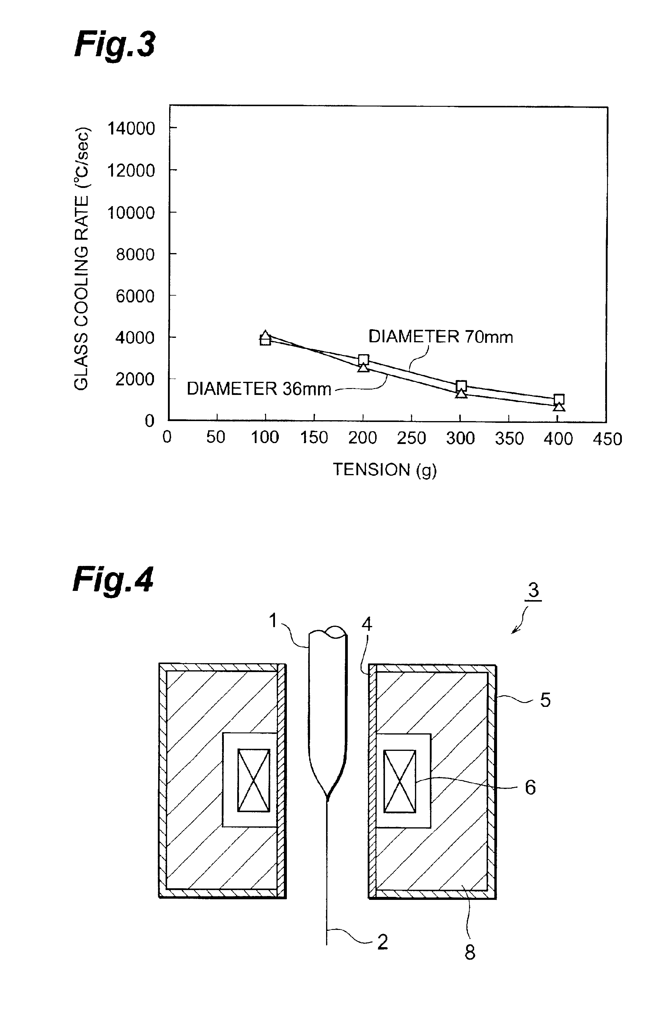
[0037]An optical fiber preform having a diameter (D) of 36 mm was inserted into a core tube of a drawing furnace having the configuration shown in FIG. 1 in which the core tube had an inner diameter (D′) of 45 mm, the furnace body had a length (L) of 250 mm in the drawing direction, and the heater had a length (H) of 130 mm in the drawing direction, and was drawn at a line speed of 100 m / min while being softened upon heating in a nitrogen atmosphere with the heater temperature being set at 1950° C., whereby an optical fiber having a diameter of 125 μm was obtained. Here, the glass cooling rate at the time when the optical fiber attained a temperature of 1800° C. was 87.41° C. / sec.

[0038]Concerning thus obtained optical fiber, the amount of change in transmission loss of light having a wavelength of 1.38 μm (Δα1.38 [dB / km]) between before and after exposure to an atmosphere of a mixed gas composed of 1% by volume of hydrogen and 99% by volume of nitrogen at 80° C. for 20 hours was mea...

examples 2 to 5

[0039]Optical fibers each having a diameter of 125 μm were prepared as in Example 1 except that the glass cooling rate at the time when the optical fibers attained a temperature of 1800° C. was changed as shown in Table 1, and Δα1.38 was measured. Table 1 shows thus obtained results.

examples 6 to 8

[0040]Optical fibers each having a diameter of 125 μm were prepared as in Example 1 except that the line speed was 200 m / min and that the glass cooling rate at the time when the optical fibers attained a temperature of 1800° C. was changed as shown in Table 1, and Δα1.38 was measured. Table 1 shows thus obtained results.

[0041]

TABLE 1Line speedGlass cooling rateΔα 1.38[m / min][° C. / sec][dB / km]Example 110087.410.000Example 210069.960.010Example 3100666.80.150Example 4100896.00.160Example 510016440.390Example 6200767.10.230Example 720013630.320Example 820030940.640


PUM

PropertyMeasurementUnit
Temperatureaaaaaaaaaa
Fractionaaaaaaaaaa
Pressureaaaaaaaaaa

Abstract

The method of manufacturing an optical fiber in accordance with the present invention comprises a step of yielding an optical fiber by drawing an optical fiber preform softened upon heating, wherein a temperature at which the optical fiber preform is softened is at least 1800° C., whereas the optical fiber preform or optical fiber has a glass cooling rate of 4000° C./sec or less when attaining a temperature of 1800° C.

Description

BACKGROUND OF THE INVENTION[0001]1. Field of the Invention[0002]The present invention relates to a method of manufacturing an optical fiber; and, more specifically, to a method of manufacturing an optical fiber in which an optical fiber preform is drawn while being softened upon heating.[0003]2. Related Background Art[0004]Optical fibers have been employed in communication lines since they have advantages over copper wire cables because of their smaller size, lighter weight, lower transmission loss, higher band transmission, and the like.[0005]A drawing furnace such as the one shown in FIG. 4 is usually used in a conventional optical fiber manufacturing step. Namely, an optical fiber preform 1 is inserted into a core tube 4 of a drawing furnace 3 and, while a leading end of the optical fiber preform 1 is softened upon heating with a heater 6 disposed about the outer periphery of the core tube 4 within a furnace body 5, the optical fiber preform 1 is drawn with a predetermined tensio...

Claims


Application Information

Patent Timeline
IPC IPC(8): C03B37/02C03B37/027C03B37/029G02B6/00
CPCC03B37/027C03B37/02718C03B37/029C03B2205/56C03B2205/63Y02P40/57
Inventor NAGAYAMA, KATSUYAKUWAHARA, KAZUYASHIMAZU, TAKAYUKI
Owner SUMITOMO ELECTRIC IND LTD
Why Eureka
Try Eureka